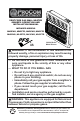
VENT-FREE GAS WALL HEATER OWNER’S OPERATION AND INSTALLATION MANUAL INFRARED MODELS MN2PHG, MN2PTG, MN3PHG, MN3PTG ML2PHG, ML2PTG, ML3PHG, ML3PTG PFS ® US 30,000 Btu/Hr Model Shown WARNING: If the information in this manual is not followed exactly, a fire or explosion may result causing property damage, personal injury or loss of life. — Do not store or use gasoline or other flammable vapors and liquids in the vicinity of this or any other appliance.
TABLE OF CONTENTS Safety......................................................... 3 Qualified Installing Agency......................... 4 Product Features........................................ 4 Specifications............................................. 5 Local Codes............................................... 7 Preparing For Installation........................... 7 Air For Combustion and Ventilation............ 8 Unpacking..................................................
SAFETY IMPORTANT: Read this owner’s manual carefully and completely before trying to assemble, operate, or service this heater. Improper use of this heater can cause serious injury or death from burns, fire, explosion, electrical shock and carbon monoxide poisoning. NATURAL AND PROPANE/LP GAS: Natural and Propane/LP gas are odorless. An odormaking agent is added to the gas. The odor helps you detect a gas leak. However, the odor added to the gas can fade. Gas may be present even though no odor exists.
SAFETY 1. Do not place Propane/LP supply tank(s) inside any structure. Propane/LP supply tank(s) must be placed outdoors. 2. Heaters with a maximum input over 6,000 Btu/Hr shall not be installed in a bathroom. Heaters with a maximum input over 10,000 Btu/Hr shall not be installed in a bedroom. 3. This heater needs fresh air ventilation to run properly. This heater has an Oxygen Depletion Sensing (ODS) safety shutoff system. The ODS shuts down the heater if not enough fresh air is available.
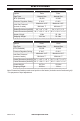
SPECIFICATIONS MODEL Ignition Gas Type MN2PHG MN2PTG Piezo Piezo Natural Gas Natural Gas BTU (available) 20,000 20,000 Pressure Regulator Setting 6" W.C. 6" W.C. Inlet Gas Pressure* (inches of water) Maximum 10.5" Maximum 10.5" Minimum 7" Minimum 7" Heater Dimensions (HxWxD) 24" × 18 1/2" × 8" 24" × 18 1/2" × 8" Carton Dimensions (HxWxD) 26 1/4" × 20 3/4" × 9 7/8" 26 1/4" × 20 3/4" × 9 7/8" Heater Weight 19 lbs 20.1 lbs Shipping Weight 22.3 lbs 23.
SPECIFICATIONS MODEL Ignition Gas Type BTU (available) Pressure Regulator Setting Inlet Gas Pressure* (inches of water) Heater Dimensions (HxWxD) ML2PHG ML2PTG Piezo Piezo Propane/LP Propane/LP 18,000 18,000 10" W.C. 10" W.C.
LOCAL CODES Install and use heater with care. Follow all local codes. In the absence of local codes, use the latest edition of The National Fuel Gas Code, ANSI Z223.1/NFPA 54*. *Available from: American National Standards Institute, Inc. 25 West 43rd Street New York, NY 10036 National Fire Protection Association, Inc. 1 Batterymarch Park Quincy, MA 02269-9101 State of Massachusetts: The installation must be made by a licensed plumber or gas fitter in the Commonwealth of Massachusetts.
UNPACKING 1. Remove heater from carton. 2. Remove all protective packaging applied to heater for shipping 3. Check heater for any shipping damage. If heater is damaged, promptly inform dealer where you bought heater. WATER VAPOR: A BY-PRODUCT OF UNVENTED ROOM HEATERS Water vapor is a by-product of gas combustion. An unvented room heater produces approximately one (1) ounce (30 mL) of water for every 1,000 BTUs (0.3 KWs) of gas input per hour.
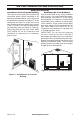
AIR FOR COMBUSTION AND VENTILATION VENTILATION AIR Ventilation Air From Inside Building This fresh air would come from an adjoining unconfined space. When ventilating to an adjoining unconfined space, you must provide two permanent openings: one within 12" of the ceiling and one within 12" of the floor on the wall connecting the two spaces (see options 1 and 2, Figure 2). You can also remove door into adjoining room (see option 3, Figure 2). Follow the National Fuel Gas Code, ANSI Z223.
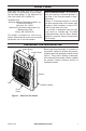
INSTALLATION NOTICE: This heater is intended for use as supplemental heat. Use this heater along with your primary heating system. Do not install this heater as your primary heat source. If you have a central heating system, you may run system’s circulating blower while using heater. This will help circulate the heat throughout the house. In the event of a power outage, you can use this heater as your primary heat source. WARNING: A qualified service person must install heater. Follow all local codes.
INSTALLATION LOCATING HEATER This heater is designed to be mounted on a wall. For convenience and efficiency, install heater: 1. Where there is easy access for operation, inspection, and service. 2. In the coldest part of room. When installing the appliance directly on carpeting, tile or other combustible material other than wood flooring, the appliance shall be installed on a metal or wood panel extended the full width and depth of the appliance. INSTALLING THERMOSTAT SENSING BULB (OPTIONAL) 1.
INSTALLATION 2. Mark screw locations on wall (see Figure 7). Note: Mark only last hole on each end of mounting bracket. Insert mounting screws through these holes only. 3. Remove tape and mounting bracket from wall. Adjoining Wall 11" Min. 12 1/4" Only Insert Mounting Screws Through Last Hole On Each End 18" Min. 20,000 BTU/Hr Heaters Non-combustible Flooring or Top of Combustible Tile Carpeting or Other Material Adjoining Wall 12 1/8" Min.
INSTALLATION Placing Heater On Mounting Bracket 1. Locate two horizontal slots on back panel of heater (see Figure 10). 2. Place heater onto mounting bracket. Slide horizontal slots onto stand-out tabs on mounting bracket. Horizontal Slots StandOut Tab 5. Replace heater onto mounting bracket. 6. Place spacers between bottom mounting holes and wall anchor or drilled hole. 7. Hold spacer in place with one hand. With other hand, insert mounting screw though bottom mounting hole and spacer.
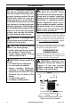
INSTALLATION CONNECTING TO GAS SUPPLY WARNING: A qualified service technician must connect heater to gas supply. Follow all local codes. WARNING: This appliance requires a 3/8" NPT (National Pipe Thread) inlet connection to the pressure regulator. WARNING: For natural gas, Never connect heater to private (non-utility) gas wells. This gas is commonly known as wellhead gas. WARNING: Do not overtighten gas connections. CAUTION: Use only new, black iron or steel pipe.
INSTALLATION Apply pipe joint sealant lightly to male threads. This will prevent excess sealant from going into pipe. Excess sealant in pipe could result in clogged heater valves. The installer must supply an external regulator. The external regulator will reduce incoming gas pressure. You must reduce incoming gas pressure to between 11" and 14" of water. If you do not reduce incoming gas pressure, heater regulator damage could occur.
INSTALLATION CHECKING GAS CONNECTIONS WARNING: Test all gas piping and connections for leaks after installing or servicing. Correct all leaks at once. WARNING: Never use an open flame to check for a leak. Apply a mixture of liquid soap and water to all joints. If bubbles form, there is a leak. Correct all leaks at once. PRESSURE TESTING GAS SUPPLY PIPING SYSTEM Test Pressures In Excess Of 1/2 PSIG (3.5 kPa) 1.
INSTALLATION PRESSURE TESTING HEATER GAS CONNECTIONS 1. Open equipment shutoff valve (see Fig- 5. Correct all leaks at once. ure 14, page 16). 6. Light heater (see Lighting Instructions on 2. Open gas supply tank valve. page 17 or 19). Check all other internal joints for leaks. 3. Make sure control knob of heater is in the 7. Turn off heater (see To Turn Off Gas ApOFF position. pliance, page 20). 4. Check all joints from equipment shutoff valve to control valve (see Figure 15 or 16, page 16).
OPERATION 7. Keep control knob pressed in for 30 seconds after lighting pilot. After 30 seconds, release control knob. If control knob does not pop up when released, contact a qualified service technician or gas supplier for repairs. Note: If pilot goes out, repeat steps 3 through 7. This heater has a safety interlock system. Wait one (1) minute before lighting pilot again. Ignitor Button Control Knob HIGH 8. Turn control knob counterclockwise to desired heating level. The main burner should light.
OPERATION THERMOSTAT MODELS LIGHTING INSTRUCTIONS CAUTION: Do not try to adjust heating levels by using the equipment shutoff valve. Ignitor Button Control Knob PIL LO OT OFF HI IGNITOR Figure 20 - Control Knob in the OFF Position Thermocouple Ignitor Electrode Pilot Burner Figure 21 - Pilot Control Knob LO PIL OT HI PIL LO 200317-01C Note: If pilot goes out, repeat steps 3 through 7. This heater has a safety interlock system. Wait one (1) minute before lighting pilot again. 8.
OPERATION THERMOSTAT CONTROL OPERATION The thermostatic control used on these models differ from standard thermostats. Standard thermostats simply turn the burner on and off. The thermostat used on this heater senses the room temperature. At times the room may exceed the set temperature. If so, the burner will shut off. The burner will cycle back on when room temperature drops below the set temperature. The control knob can be set to any comfort level between HI and LO.
INSPECTING BURNERS IMPORTANT: Owner’s should check pilot flame pattern and burner flame pattern often. Incorrect flame patterns indicate the need for cleaning (see Care and Maintenance, page 22) or service. WARNING: Only a qualified service person should service and repair heater. This includes maintenance requiring replacement or alteration of components. PILOT FLAME PATTERN Figure 24 shows a correct pilot flame pattern. Figure 25 shows an incorrect pilot flame pattern.
CARE AND MAINTENANCE WARNING: Turn off heater and let cool before servicing. CAUTION: You must keep control areas, burner, and circulating air passageways of heater clean. Inspect these areas of heater before each use. Have heater inspected yearly by a qualified service technician. Heater may need more frequent cleaning due to excessive lint from carpeting, bedding material, pet hair, etc. WARNING: Failure to keep the primary air opening(s) of the burner(s) clean may result in sooting and property damage.
TROUBLESHOOTING WARNING: If you smell gas: • Shut off gas supply. • Do not try to light any appliance. • Do not touch any electrical switch; do not use any phone in your building. • Immediately call your gas supplier from a neighbor’s phone. Follow the gas supplier’s instructions. • If you cannot reach your gas supplier, call the fire department. WARNING: Only a qualified service technician should service and repair heater. Make sure that power is turned off before proceeding.
TROUBLESHOOTING Problem Possible Cause Corrective Action ODS/pilot lights but flame 1. Control knob is not fully 1. Press in control knob fully. goes out when control pressed in. knob is released. 2. Control knob is not pressed 2. After ODS/pilot lights, keep in long enough. control knob pressed in 30 seconds. 3. Equipment shutoff valve is 3. Fully open equipment shutoff not fully open. valve. 4. Thermocouple connection is 4. Hand tighten until snug, and loose at control valve.
TROUBLESHOOTING Problem Possible Cause Corrective Action Heater produces a whis- 1. Turning control knob to the 1. Turn control knob to the low tling noise when burner high position when burner is position and let warm up for is lit. cold. a minute. 2. Air in gas line. 2. Operate burner until air is removed from line. Have gas line checked by local gas supplier. 3. Air passageways on heater 3 Observe minimum installation are blocked. clearances (Figure 4, page 10). 4.
PARTS MODELS MN2PHG, ML2PHG, MN3PHG, ML3PHG 30,000 BTU/Hr Heater Shown 10 2 3 11 15 1 14 12 4 5 6 7 16 9 8 13 26 www.usaprocom.
PARTS MODELS MN2PHG, ML2PHG, MN3PHG, ML3PHG This list contains replaceable parts for your heater. When ordering replacement parts, follow the instructions listed under Replacement Parts on page 30 of this manual.
PARTS MODELS MN2PTG, ML2PTG, MN3PTG, ML3PTG 30,000 BTU/Hr Heater Shown 11 2 3 16 1 15 13 4 5 6 8 7 10 12 9 17 14 28 www.usaprocom.
PARTS MODELS MN2PTG, ML2PTG, MN3PTG, ML3PTG This list contains replaceable parts for your heater. When ordering replacement parts, follow the instructions listed under Replacement Parts on page 30 of this manual.
REPLACEMENT PARTS Note: Use only original replacement parts. This will protect your warranty coverage for parts replaced under warranty. PARTS UNDER WARRANTY Contact authorized dealers of this product. If they can’t supply original replacement parts, call Customer Service toll free at 1-866-573-0674 for referral information.
ACCESSORIES Purchase these heater accessories from your local dealer. If they can not supply these accessories, contact ProCom Heating, Inc. at 1-866-573-0674 for information. EQUIPMENT SHUTOFF VALVE For all models. Equipment shutoff valve with 1/8" NPT tap. OPTIONAL FAN KIT - MGB100 The optional fan has 3 settings AUTO/OFF/MAN. Please refer to MGB100 instructions for operation. FLOOR MOUNTING STAND - PF09B For locating heater on the floor, away from a wall.
WARRANTY KEEP THIS WARRANTY Model ________________________________ Serial No. _____________________________ Date Purchased ________________________ Keep receipt for warranty verification. REGISTER YOUR PRODUCT AT WWW.USAPROCOM.COM IMPORTANT: We urge you to register your product within 10 days of date of installation, complete with entire serial number which can be found on the rating plate. Please fill out the warranty information above for your personal records. Retain this manual for future reference.