
Full Product Manual


www.usaprocom.com
13200067-01A
INSTALLATION
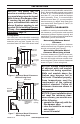
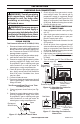
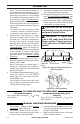
Figure 11 - Attaching Heater Base to
Fireplace Floor
Masonry
Screw
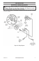
Connecting
Wire
Connecting
Port
Battery Case
Ignitor
Receiver
WARNING: You must secure
this heater to replace oor. If
not, heater will move when you
adjust controls. Moving heater
may cause a gas leak.
WARNING: If installing in a
sunken replace, special care
is needed. You must raise the
replace oor to allow access to
heater control panel. This will in-
sure adequate air ow and guard
against sooting and controls
being damaged. Raise replace
oor with noncombustible mate-
rial. Make sure material is secure.
CAUTION: Do not pick up
heater base assembly by burn-
ers. This could damage heater.
Only handle base assembly by
grates.
IMPORTANT: Make sure the heater burners
are level. If heater is not level, heater will not
work properly.
Installation Items Needed
• hardware package (provided with heater)
• electric drill with 3/16" masonry drill bit
1. Position heater base assembly in re-
place. Center base assembly left to right
and front to back inside replace.
2. Mark screw locations through holes in
mounting brackets (see Figure 11). If
installing in a brick-bottom replace, mark
screw locations in mortar joint of bricks.
3. Remove heater base from replace.
4. Drill holes at marked locations using 3/16"
drill bit.
5. Apply pipe joint sealant lightly to tting
threads. Connect approved exible gas
hose to gas regulator of heater (see Figure
11). Note: Never apply pipe sealant to are
tting threads. Hold gas regulator with a
wrench when connecting exible gas hose.
6. Attach base assembly to replace oor
using two masonry screws provided in
hardware package (see Figure 11).
7. Connect to gas supply. See Connecting
To Gas Supply, page 14.
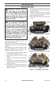
INSTALLING HEATER BASE ASSEMBLY
RECEIVER INSTALLATION
Insert one side of the connecting wire port into
the chassis (black and green line). Insert the
other side into the receiver port (see Figure 11).
BATTERY CASE INSTALLATION
Insert the bagttery case port into the ambiance
light connecting port (see Figure 11).
BATTERY INSTRUCTIONS
CAUTION: Do not mix old and
new batteries. Do not mix alka-
line, standard (carbon - zinc), or
rechargeable (nickel - cadmium)
batteries. Do not dispose of
batteries in re, batteries may
explode or leak.
• Batteries are included.
• Remove batteries when depleted.
• Be sure to observe proper polarity (+/-)
when installing or replacing the batteries.
Damage due to improper battery installa-
tion may void the warranty on the product.
• For long periods of non-operation, remove
batteries from all components for safety.
1. Unscrew ignitor cap and install a AAA bat-
tery with the + pointing out. Replace cap.
2. Install 4 AA batteries into receiver case,
and place case aside, away from chassis
(where batteries can easily be changed).
3. Install 2 D size batteries into battery case.
Place battery case to the side, away from
chassis (where batteries can easily be
changed).