NATURAL GAS LOG VENTED DECORATIVE APPLIANCE MODELS WAN18LA WAN24LA PFS ® US WARNING: If the information in this manual is not followed exactly, a fire or explosion may result causing property damage, personal injury or loss of life. — Do not store or use gasoline or other flammable vapors and liquids in the v icinity of this or any other appliance. — WHAT TO DO IF YOU SMELL GAS • Do not try to light any appliance. • Do not touch any electrical switch; do not use any phone in your building.
TABLE OF CONTENTS Specifications............................................. 3 Safety......................................................... 3 Product Features........................................ 5 Local Codes............................................... 5 Unpacking.................................................. 5 Air For Combustion and Ventilation............ 6 Installation.................................................. 6 Operation..................................................
SPECIFICATIONS Note: This vented appliance must be installed only in a solid-fuel burning fireplace with a working flue and constructed of noncombustible material. The charts indicate technical information regarding the installation of your gas log set. Model Gas Type BTU Input* Minimum Vent Opening Burner Orifice (Propane/LP)** Please make sure that all of the specifications shown are applicable before installation is attempted.
SAFETY WARNING: Any change to this log set or its controls can be dangerous. 1. This appliance, as supplied, is only for use with the type of gas indicated on the rating plate. This appliance is convertible for use with propane/LP, using the manual ON/OFF safety pilot valve kit. 2. If you smell gas: • Shut off gas supply • Do not try to light any appliance • Do not touch any electrical switches; do not use any phone in your building • Immediately call your gas supplier from a neighbor's phone.
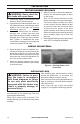
PRODUCT FEATURES ON/OFF SAFETY PILOT VALVE KIT WITH PROPANE/LP CONVERSION An optional on/off valve/safety pilot kit with a piezo ignitor is available for this appliance. This system requires no matches, batteries, or other sources to light. You must use this optional system for Propane/LP conversion. LOCAL CODES Install and use heater with care. Follow all local codes. In the absence of local codes, use the latest edition of The National Fuel Gas Code, ANSI Z223.1/NFPA 54*.
AIR FOR COMBUSTION AND VENTILATION WARNING: If the area in which the heater may be operated does not meet the required volume for indoor combustion air, combustion and ventilation air shall be provided by one of the methods described in the National Fuel Gas Code, ANSI Z223.1/NFPA 54, the International Fuel Gas Code, or applicable local codes. Today's homes are built more energy efficient than ever. New materials, increased insulation, and new construction methods help reduce heat loss in homes.
INSTALLATION INSTALLING DAMPER CLAMP Secure the damper stop clamp provided to the leading edge of the damper as shown in Figure 2. If for any reason this clamp doesn't work on your fireplace, another suitable clamp or permanent stop must be installed, or the damper blade must be cut or removed. Damper Clamp Damper Damper Damper Masonry Fireplace Manufactured Fireplace Figure 2 - Attaching Damper Clamp HEARTH KIT ASSEMBLY Note: The following instructions apply to dual flame "U" style burners.
INSTALLATION Installation and Gas Connection 1. Place the burner pan assembly in the center of the fireplace floor. Make sure the front of pan faces forward. 2. Thread the gas supply fitting to the fireplace gas supply pipe. Use thread sealant. 3. Install adapter fitting onto the burner inlet fitting using thread sealant on male threads of burner inlet fitting (see Figure 4). 4. Install the gas connector tube to the gas supply fitting. Carefully shape tube to attach to adapter fitting.
INSTALLATION CHECKING GAS CONNECTIONS WARNING: Test all gas piping and connections for leaks after installing or servicing. Correct all leaks immediately. WARNING: Never use an open flame to check for a leak. Apply a noncorrosive leak detection fluid to all joints. Bubbles forming show a leak. Correct all leaks immediately. PRESSURE TESTING GAS SUPPLY PIPING SYSTEM Test Pressures In Excess Of 1/2 PSIG ( 3.5kPa ) 1.
INSTALLATION TESTING BURNER FOR LEAKS WARNING: Never check for gas leaks with open flame. 1. Generously apply a noncorrosive leak detection fluid to all connections. 2. Light the burner with the shutoff valve, no more than half open, and holding a match slightly in front of the pan (see Lighting Instructions, page 13). 3. Inspect all connections for bubbles, raw gas odor, or flame from any area other than the burner (leaks). If leaks are detected, shut off the gas valve immediately.
INSTALLATION MODEL WAN18LA 1. Slide the two rear log grate steps over the two outer horizontal supports on the grate as shown in Figure 10. 2. Place back log #1 onto the grate steps (see Figure 11). 3. Place front logs #2 and #3 on the grate and slide forward against the front bars on the grate (see Figure 12). 4. Place logs #4 and #5 onto logs #1, #2 and #3 by inserting locating pin on log #1 into lower hole of logs #4 and #5 (see Figure 13). 5.
INSTALLATION MODEL WAN24LA 1. Slide the two rear log grate steps over the two outer horizontal supports on the grate as shown in Figure 15. 2. Place back log #1 onto the grate steps (see Figure 16). 3. Place front logs #2 and #3 on the grate and slide forward against the front bars on the grate (see Figure 17). 4. Place logs #4 and #5 onto logs #1, #2 and #3 by inserting locating pin on log #1 into lower hole of logs #4 and #5 (see Figure 18). 5.
OPERATION FOR YOUR SAFETY READ BEFORE LIGHTING WARNING: If you do not follow these instructions exactly, a fire or explosion may result causing property damage, personal injury or loss of life. A. This appliance has a pilot which must be lighted by hand. When lighting the pilot, follow these instructions exactly. B. BEFORE LIGHTING smell all around the appliance area for gas. Be sure to smell next to the floor because some gas is heavier than air and will settle on the floor.
CARE AND MAINTENANCE • Keep the area around the log set clean and clear of debris. • Occasionally, you may use a soft bristle brush to clean logs. • Once every year a qualified agency or certified chimney sweep should examine and clean the venting system of the fireplace. ACCESSORIES Purchase these fireplace accessories from your local dealer. If they can not supply these accessories, contact customer service department for information. EQUIPMENT SHUTOFF VALVE For all models.
TROUBLESHOOTING WARNING: If you smell gas: • Shut off gas supply. • Do not try to light any appliance. • Do not touch any electrical switch; do not use any phone in your building. • Immediately call your gas supplier from a neighbor’s phone. Follow the gas supplier’s instructions. • If you cannot reach your gas supplier, call the fire department. WARNING: Only a qualified service technician should service and repair heater. Make sure that power is turned off before proceeding.
TROUBLESHOOTING Problem Possible Cause Corrective Action Log set produces a click- 1. Metal expanding while heat- 1. This is common with most ing/ticking noise just after ing or contracting while coollog sets. If noise is excesburner is lit or shut off. ing. sive, contact qualified service person. Log set produces un- 1. Log Set burning vapors 1. Open flue to maximum. Stop wanted odors. from paint, hair spray, glues, using odor causing products cleaners, chemicals, new while log set is running.
REPLACEMENT PARTS Note: Use only original replacement parts. This will protect your warranty coverage for parts replaced under warranty. PARTS UNDER WARRANTY Contact authorized dealers of this product. If they can’t supply original replacement parts, call Customer Service toll free at 1-866-573-6074 for referral information.
PARTS MODELS WAN18LA AND WAN24LA 4 4 3 2 1 ITEM 1 2 3 4 WAN18LA BL050-01 WAL06-01 WAL07-01N WAB18-01 WAN24LA BL050-01 WAL06-01 WAL07-02N WAB18-01 DESCRIPTION QTY 3/8" Female x 5/8" Flare Adapter 1 Injector Mounting 1 Injector 1 Grate Step 2 PARTS AVAILABLE - NOT SHOWN WAL11-01 Vermiculite GLEMVERM25 Glowing Embers WAN300B Hardware Package WAL08-02 1/2" Female x 5/8" Flare Adapter WAL13-01 Damper Clamp 18 www.usaprocom.
PARTS MODELS WAN18LA AND WAN24LA This list contains replaceable parts used in your heater. When ordering parts, follow the instructions listed under Replacement Parts on page 17 of this manual. WAN18LA WAB04 Log Assembly WAN18LA-1 Log 1 WAN18LA-2 Log 2 WAN18LA-3 Log 3 WAN18LA-4 Log 4 WAN18LA-5 Log 5 WAN18LA-6 Log 6 WAN18LA-7 Log 7 200063-01A WAN24LA WAB06 Log Assembly WAN24LA-1 Log 1 WAN24LA-2 Log 2 WAN24LA-3 Log 3 WAN24LA-4 Log 4 WAN24LA-5 Log 5 WAN24LA-6 Log 6 WAN24LA-7 Log 7 WAN24LA-8 Log 8 www.
WARRANTY KEEP THIS WARRANTY Model ________________________________ Serial No. _____________________________ Date Purchased ________________________ Keep receipt for warranty verification. REGISTER YOUR PRODUCT AT WWW.USAPROCOM.COM IMPORTANT: We urge you to register your product within 10 days of date of installation, complete with entire serial number which can be found on the rating plate. Please fill out the warranty information above for your personal records. Retain this manual for future reference.