
Instruction Manual

AAC 1/...
Active Receiving Antenna for 10 kHz - 110 MHz for
Communication Purposes
DESCRIPTION
This active receiving antenna has been designed for professional use
and special emphasis has been placed on obtaining a large dynamic
range with excellent cross and intermodulation properties, a low noise
figure and a secure protection against RF-overload and violent nearby
discharges.
The AAC 1/... can be used either where superb listening quality is
required or where a high RF-density environment exists, as for instance
in connection with MF and HF duplex operation onboard ships, where
nearby transmitting antennas may cause excessive field strengths. For
complete safety the antenna should, however, not be mounted closer
than 15 metres from transmitting antennas.
The antenna consists of a high-capacitance glass fibre antenna element
and an amplifier built into the antenna mount. The amplifier provides
the necessary impedance matching between the high-impedance
antenna element and the 50 Ω downlead cable over an extremely wide
bandwidth.
The necessary supply voltage (12 – 15 V DC) for the amplifier is
delivered through the downlead coaxial cable from the junction box
with mains power supply, type JB 230 (230 VAC) or JB 115 (115 VAC),
which separates DC and RF-signals. Up to 200 m of RG 213/U
coaxial cable can be used between antenna and junction box
with only minor degrading effects.
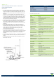
The earthing wire (see drawing) ensures a low loss connection to
ground for RF-signals, and thereby also prevents noise pick-up from the
ship’s installations running on the outside of the coaxial cable. As the
earthing wire is AC-coupled, electrolytic corrosion is effectively
prevented.
By careful choice of materials, the AAC 1/... is designed to withstand the
roughest of climate conditions, ensuring many years of trouble-free
service.
Extended amplifier frequency range makes it possible also to receive
FM-radio (88 – 108 MHz).
ORDERING DESIGNATIONS
TYPE PRODUCT NO.
AAC 1/JB 230 100000160
AAC 1/JB 115 100000438
Junction box JB 230 110000009
Junction box JB 115 110000264
ANTENNA SPECIFICATIONS
ELECTRICAL
MODEL AAC 1/...
ANTENNA TYPE Broadband active receiving antenna for
communication purposes
FREQUENCY 10 kHz – 110 MHz
IMPEDANCE Nom. 50 Ω
POLARIZATION Vertical
HORIZONTAL COVER. Omni-directional
ANTENNA FACTOR Typ. 0.25 mV output in 50 Ω by a field strength of
1 mV/m
1 dB COMPRESSION
POINT
Typ. occurring at a field strength of 1.5 V/m
1 dB QUIETING Typ. occurring at a field strength of 1 V/m from an
interfering signal
CROSS MODULATION 40 dB cross modulation attenuation typically
occurring at a field strength of 0.7 V/m from an
interfering source
INTERMODULATION
OIP 2 > 40 dBm
OIP 3 > 27 dBm
MAX. ALLOWED FIELD
STRENGTH
90 V/m
AMPLIFIER PROTECTION Spark gap
OPERATING VOLTAGE 12 – 15 V DC (with JB 230 or JB 115)
CURRENT CONSUMP. Approx. 60 mA
MECHANICAL
TEMP. RANGE -30° C → +60° C
CONNECTOR N-female
WIND SURFACE 0.0259 m²
WIND LOAD 28.8 N @ 150 km/h
COLOUR Marine white
MATERIALS Shroud: Glass fibre and chromed brass
MA housing: Lexan amd chromed brass
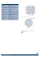
TOTAL HEIGHT Approx. 0.92 m / 36.22 in.
DIA. IN TOP END 7 mm / 0.28 in.
DIA. IN BOTTOM END 10 mm / 0.39 in.
WEIGHT Approx. 600 g / 1.32 lb.
MOUNTING On flat surfaces such as deck or roof or on 30 – 44
mm mast tube using accessory item “SM-MA” (not
included)