
Instruction Manual

BPF 4/...-200
Band-Pass Filters for the 80 MHz Band
DESCRIPTION
High power base station band-pass filters for the 66 – 88 MHz range.
The use of large ø200 mm cavities means a high Q, resulting in a very
narrow passband.
The large dimensions also mean a high power rating.
Unloaded Q of a single cavity is approx. 7000.
High frequency stability on temperature and power.
19” mounting brackets are available as an option.
ORDERING DESIGNATIONS
TYPE PRODUCT NO.
BPF 4/1-200 200000989
BPF 4/2-200 200001166
BPF 4/3-200 200001882
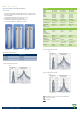
TYPICAL RESPONSE CURVES
Figure 1
SPECIFICATIONS
ELECTRICAL
MODEL BPF 4/1-200 BPF 4/2-200 BPF 4/3-200
FREQ.
RANGE
66 - 88 MHz 66 - 88 MHz 66 - 88 MHz
MAX.
INPUT
POWER
350 W @
0.5 dB IL
150 W @
2.0 dB IL
350 W @
1.0 dB IL
150 W @
4.0 dB IL
350 W @
1.5 dB IL
150 W @
6.0 dB IL
INSERTION LOSS Adjustable
0.4 - 2.0 dB
Adjustable
0.8 - 4.0 dB
Adjustable
1.2 - 6.0 dB
ATTENUATION See figure 1 See figure 2 See figure 3
IMPEDANCE Nom. 50 Ω Nom. 50 Ω Nom. 50 Ω
SWR
(at resonance)
≤ 1.5 ≤ 1.5 ≤ 1.5
MECHANICAL
TEMP.
RANGE
RH 0-90%
non-condensing
–30° C →
+60° C
–30° C →
+60° C
–30° C →
+60° C
FREQ.
STABILITY
Approx. 1.5
ppm/° C
Approx. 1.5
ppm/° C
Approx. 1.5
ppm/° C
MAX. RPM 200 (On tuning rod)
CONNECTORS N-female N-female N-female
DIMENSIONS ø200 x 1200 mm L:200 x W:400 x
H:1200 mm
L:200 x W:600 x
H:1200 mm
WEIGHT Approx.
6.7 kg
Approx.
13.7 kg
Approx.
20.9 kg
TYPICAL RESPONSE CURVES
Figure 2
TYPICAL RESPONSE CURVES
Figure 3
PROCOM A/S reserve the right to amend specifications
without prior notice.
04/10/13