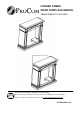
CORNER COMBO WOOD FIREPLACE MANTEL Model #FBD28TCC-M-HC/MO Questions about installation, Operation or troubleshooting? Before returning to your retailer, contact our customer service department at 1-877-886-5989, 8:00a.m.—4:30p.m., EST, Monday—Friday or e-mail customerservice@usaprocom.com.
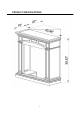
PRODUCT SPECIFICATIONS 2
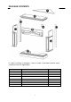
PACKAGE CONTENTS If a part is missing or damaged - return to place of purchase (exterior wood components are not replaceable).
HARDWARE CONTENTS Part Description AA Cam Dowel 16 BB Cam Lock 16 CC Wall Anchor Quantity ST4 Screw DD 1 -3/16 in. ST5 Screw EE 2- 3/8 in. Picture (Shown to size) Part FF GG BB 2 HH 8 II Description ST4 Screw 5/8 in. Connector Bracket White Key ST4 Screw 1 -9/16 in. Quantity Picture (Shown to size) 18 3 1 8 2 WARNINGS AND CAUTIONS WARNING y When tightening screws, do not over tighten, this may cause threads to strip.
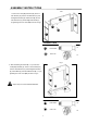
ASSEMBLY INSTRUCTIONS Fig 1 1. Insert Cam Locks (BB) into Panel (B). Screw in Cam Dowels (AA) into the Left Side Panel (C) and the Right Side Panel (D). Attach Panel (B) into the Left Side Panel (C) and the Right Side Panel (D) by tightening the Cam Locks (BB) as shown in Fig1. Hardware Used AA Cam Dowel BB Cam Lock ×4 ×4 Fig 2 2. After assembling the mantel (B, C, D), insert Cam Locks (BB) into Base (E), screw in Cam Dowels (AA) into the Left Side Panel (C) and the Right Side Panel (D).
Fig 3 3. Insert Cam Locks (BB) into assembled frame (B, C, D). Screw in Cam Dowels (AA) into the Top (A). Attach Top (A) into assembled frame (B, C, D, E) by tightening the Cam Locks (BB) as shown in Fig 3. Fasten the batten with ST4 Screw 1-9/16 in. (II) to the Top (A) and the Base (E) as shown in Fig 3. Hardware Used AA Cam Dowel BB Cam Lock II 4. Place insert into the mantel as shown in Fig 4. Fig 4 6 ST4 Screw 1 -9/16 in.
FOR CORNER APPLICATION Fig 5 5. Turn the fireplace Top (A) Panel over. Using the Connector Brackets (GG) that supplied, connect the Fireplace Top (A) to the Top Triangle Panel (H) with ST4 Screw 5/8 in. (FF) as shown in Fig 5. Hardware Used FF GG ST4 Screw ×18 5/8 in. Connector Bracket ×3 Fig 6 6. Insert Cam Locks (BB) into assembled frame (B, C, D).Screw in Cam Dowels (AA) into the Top (A). Attach Top (A) into assembled frame (B, C, D, E) by tightening the Cam Locks (BB) as shown in Fig 6.
Fig 7 7. Attach the left and right Backboard (I) trim pieces to the back of the fireplace with ST4 Screw 1-3/16 in. (DD) as shown in Fig 7. Hardware Used AA DD ST4 Screw ×8 1 -3/16 in. BB Fig 8 8. Drill two holes (5/16 in.) in the corner where the fireplace is to be displayed. Drill the first hole 37-7/8 in. from the ground up, and the second hole 1-9/16 in. from the first hole as shown in Fig 8. Put the Wall Anchor (CC) in the holes by pinching the anchor tabs together as shown in Fig 8.
Fig 9 9. Attach the triangular wood block to the holes drilled in step 8 with ST5 Screw 2-3/8 in. (EE) as shown in Fig 9. This block is used to support the Set Square Support (J). For thin walls, insert white key (HH) into wall anchor and push to “pop” open anchor wings. Hardware Used EE HH ST5 Screw 2 3/8 in. White Key ×2 ×1 10. Push fireplace into corner so that the Top Triangle Panel (F) is resting on top of the Set Square Support (H) as shown in Fig 10.
REPLACEMENT PARTS LIST Part Description Part # Quantity Hardware Package HP006 1 AA Cam Dowel PCAM-023 16 BB Cam Lock PCAM-023 16 CC Wall Anchor ML066-01 2 DD ST4 Screw 1-3/16 in. GB/T 951 4×30 8 EE ST5 Screw 2-3/8 in. GB/T 950 5×60 2 FF ST4 Screw 5/8 in. GB/T 951 4×16 18 GG Connector Bracket SJ002 3 HH White Key ML067-01 1 II ST4 Screw 1-9/16 in.
WARRANTY INFORMATION Keep This Warranty IMPORTANT: We urge you to fill your warranty registration card within TEN(10) days of date of installation, complete with the entire serial number which can be found on the rating plate. Retain this portion of the card for your record. Always specify model and serial numbers when communicating with customer service. We reserve the right to amend these specifications at any time without notice. The only warranty applicable is our standard written warranty.