
Use and Care Manual


www.usaprocom.com
200045-01B14
INSTALLATION
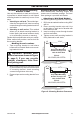
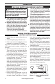
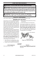
Figure 14 - External Regulator
with Vent Pointing Down
External
Regulator with
Vent Pointing
Down
Propane/LP
Supply Tank
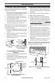
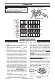
Figure 13 - Gas Connection
* Purchase the optional CSA design-certied
equipment shutoff valve from your dealer.
Equipment
Shutoff Valve
Ground
Joint Union
Pressure
Regulator
3/8" NPT
Pipe Nipple
Tee Joint
Reducer
Bushing to
1/8" NPT
1/8" NPT
Plug Tap
Test Gauge
Connection*
Sediment
Trap
Tee Joint
Pipe Nipple
Cap
3" Minimum
From External
Regulator
(11" W.C. to
14" W.C.
Pressure)
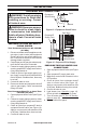
Typical Inlet Pipe Diameters
Models up to 20,000 BTU/hr use 3/8" black
iron pipe or greater. Models 25,000 BTU/hr
and higher use 1/2" black iron pipe or greater.
Installation must include an equipment shutoff
valve, union, and plugged 1/8" NPT tap. Lo-
cate NPT tap within reach for test gauge hook
up. NPT tap must be upstream from heater
(see Figure 13).
IMPORTANT: Install an equipment shutoff
valve in an accessible location. The equip-
ment shutoff valve is for turning on or shutting
off the gas to the appliance.
Apply pipe joint sealant lightly to male threads.
This will prevent excess sealant from going
into pipe. Excess sealant in pipe could result
in clogged heater valves.
The installer must supply an external regula-
tor. The external regulator will reduce incom-
ing gas pressure. You must reduce incoming
gas pressure to between 11" and 14" of water.
If you do not reduce incoming gas pressure,
heater regulator damage could occur. Install
external regulator with the vent pointing down
as shown in Figure 14. Pointing the vent down
protects it from freezing rain or sleet.
Install sediment trap in supply line as shown
in Figure 13. Place sediment trap where it is
within reach for cleaning. Place sediment trap
where trapped matter is not likely to freeze.
A sediment trap traps moisture and contami-
nants. This keeps them from going into heater
controls. If sediment trap is not installed or is
installed wrong, heater may not run properly.