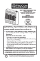
BLUE FLAME VENT-FREE PROPANE/LP GAS SPACE HEATER OWNER’S OPERATION AND INSTALLATION MANUAL MODELS ML200HBA, ML200TBA ML300HBA, ML300TBA WARNING: If the information in this manual is not followed exactly, a fire or explosion may result causing property damage, personal injury or loss of life. — Do not store or use gasoline or other flammable vapors and liquids in the v icinity of this or any other appliance. — WHAT TO DO IF YOU SMELL GAS • Do not try to light any appliance.
TABLE OF CONTENTS Safety......................................................... 3 Specifications............................................. 4 Product Identification.................................. 5 Qualified Installing Agency......................... 5 Product Features........................................ 5 Air For Combustion and Ventilation............ 6 Local Codes............................................... 6 Unpacking..................................................
SAFETY IMPORTANT: Read this owner’s manual carefully and completely before trying to assemble, operate, or service this heater. Improper use of this heater can cause serious injury or death from burns, fire, explosion, electrical shock and carbon monoxide poisoning. Only a qualified installer, service agent, or local gas supplier may install and service this product. WARNING: Keep the appliance area clear and free from combustible materials, gasoline, and other flammable vapors and liquids.
SAFETY 1. Do not place Propane/LP supply tank(s) inside any structure. Propane/LP supply tank(s) must be placed outdoors. 2. This heater shall not be installed in a bathroom or a bedroom. 3. This heater needs fresh air ventilation to run properly. This heater has an Oxygen Depletion Sensing (ODS) safety shutoff system. The ODS shuts down the heater if not enough fresh air is available. See Air for Combustion and Ventilation, pages 6 and 7. If heater keeps shutting off, see Troubleshooting, page 20. 4.
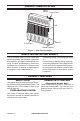
PRODUCT IDENTIFICATION Ignitor Button Control Knob Grill Burners Front Panel Heater Cabinet Figure 1 - Vent-Free Gas Heater QUALIFIED INSTALLING AGENCY Only a qualified agency should install and replace gas piping, gas utilization equipment or accessories, and repair and equipment servicing.
LOCAL CODES Install and use heater with care. Follow all local codes. In the absence of local codes, use the latest edition of The National Fuel Gas Code, ANSI Z223.1/NFPA 54*. *Available from: American National Standards Institute, Inc. 1430 Broadway New York, NY 10018 National Fire Protection Association, Inc. 1 Batterymarch Park Quincy, MA 02269-9101 State of Massachusetts: The installation must be made by a licensed plumber or gas fitter in the Commonwealth of Massachusetts.
AIR FOR COMBUSTION AND VENTILATION Exhaust fans, fireplaces, clothes dryers and fuel burning appliances draw air from the house to operate. You must provide adequate fresh air for these appliances. This will insure proper venting of vented fuel-burning appliances. WARNING: This heater shall not be installed in a room or space unless the required volume of indoor combustion air is provided by the method described in the National Fuel Gas Code, ANSI Z223.
INSTALLATION NOTICE: This heater is intended for use as supplemental heat. Use this heater along with your primary heating system. Do not install this heater as your primary heat source. If you have a central heating system, you may run system’s circulating blower while using heater. This will help circulate the heat throughout the house. In the event of a power outage, you can use this heater as your primary heat source.
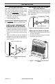
INSTALLATION LOCATING HEATER FASTENING HEATER TO WALL This heater is designed to be mounted on a wall. You can locate heater on the floor, away from a wall. An optional floor mounting stand is needed. See Accessories, page 23. For convenience and efficiency, install heater: 1. Where there is easy access for operation, inspection, and service. 2. In the coldest part of room. An optional fan kit is available from your dealer See Accessories, page 23.
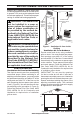
INSTALLATION Methods For Attaching Mounting Bracket To Wall Use only the last hole on each end of mounting bracket to attach bracket to wall. Attach mounting bracket to a wall only in one of two ways: 1. Attaching to wall stud: This method provides the strongest hold. Insert mounting screws through mounting bracket and into wall studs. 2. Attaching to wall anchor: This method allows you to attach mounting bracket to hollow walls (wall areas between studs) or to solid walls (concrete or masonry).
INSTALLATION 5. Place mounting bracket onto wall. Line up last hole on each end of bracket with wall anchors. 6. Insert mounting screws through bracket and into wall anchors. 7. Tighten screws until mounting bracket is firmly fastened to wall. Placing Heater On Mounting Bracket 1. Locate two horizontal slots on back panel of heater (see Figure 11). 2. Place heater onto mounting bracket. Slide horizontal slots onto stand-out tabs on mounting bracket.
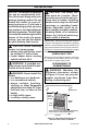
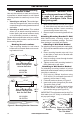
INSTALLATION CONNECTING TO GAS SUPPLY WARNING: A qualified service technician must connect heater to gas supply. Follow all local codes. CAUTION: Avoid damage to regulator. Hold gas regulator with wrench when connecting into gas piping and/or fittings. WARNING: This appliance requires a 3/8" NPT (National Pipe Thread) inlet connection to the pressure regulator. CAUTION: Use pipe joint sealant that is resistant to propane/ LP gas. WARNING: Do not overtighten gas connections.
INSTALLATION Typical Inlet Pipe Diameters Models up to 20,000 BTU/hr use 3/8" black iron pipe or greater. Models 25,000 BTU/hr and higher use 1/2" black iron pipe or greater. Installation must include an equipment shutoff valve, union, and plugged 1/8" NPT tap. Locate NPT tap within reach for test gauge hook up. NPT tap must be upstream from heater (see Figure 13). IMPORTANT: Install an equipment shutoff valve in an accessible location.
INSTALLATION CHECKING GAS CONNECTIONS WARNING: Test all gas piping and connections for leaks after installing or servicing. Correct all leaks at once. WARNING: Never use an open flame to check for a leak. Apply a noncorrosive leak detection fluid to all joints. If bubbles form, there is a leak. Correct all leaks at once. PRESSURE TESTING GAS SUPPLY PIPING SYSTEM Test Pressures In Excess Of 1/2 PSIG (3.5 kPa) 1.
OPERATION FOR YOUR SAFETY READ BEFORE LIGHTING WARNING: If you do not follow these instructions exactly, a fire or explosion may result causing property damage, personal injury or loss of life. A. This appliance has a pilot which must be lighted by hand. When lighting the pilot, follow these instructions exactly. B. BEFORE LIGHTING smell all around the appliance area for gas. Be sure to smell next to the floor because some gas is heavier than air and will settle on the floor.
OPERATION CAUTION: Do not try to adjust heating levels by using the equipment shutoff valve. Thermocouple Ignitor Electrode Pilot Burner Figure 18 - Pilot THERMOSTAT MODELS LIGHTING INSTRUCTIONS LO CAUTION: Do not try to adjust heating levels by using the equipment shutoff valve. Ignitor Button IH PIL 16 Also contact a qualified service technician or gas supplier for repairs. Until repairs are made, light pilot with match. To light pilot with match, see Manual Lighting Procedure, page 17. 7.
OPERATION THERMOSTAT CONTROL OPERATION The thermostatic control used on these models differ from standard thermostats. Standard thermostats simply turn the burner on and off. The thermostat used on this heater senses the room temperature. At times the room may exceed the set temperature. If so, the burner will shut off. The burner will cycle back on when room temperature drops below the set temperature. The control knob can be set to any comfort level between HI and LO.
INSPECTING HEATER IMPORTANT: Owner’s should check pilot flame pattern and burner flame pattern often. Incorrect flame patterns indicate the need for cleaning (see Care and Maintenance, page 19) or service. WARNING: Only a qualified service person should service and repair heater. This includes maintenance requiring replacement or alteration of components. PILOT FLAME PATTERN Figure 20 shows a correct pilot flame pattern. Figure 21 shows an incorrect pilot flame pattern.
CARE AND MAINTENANCE WARNING: Turn off heater and let cool before servicing. CAUTION: You must keep control areas, burner, and circulating air passageways of heater clean. Inspect these areas of heater before each use. Have heater inspected yearly by a qualified service technician. Heater may need more frequent cleaning due to excessive lint from carpeting, bedding material, pet hair, etc. WARNING: Failure to keep the primary air opening(s) of the burner(s) clean may result in sooting and property damage.
TROUBLESHOOTING WARNING: If you smell gas: • Shut off gas supply. • Do not try to light any appliance. • Do not touch any electrical switch; do not use any phone in your building. • Immediately call your gas supplier from a neighbor’s phone. Follow the gas supplier’s instructions. • If you cannot reach your gas supplier, call the fire department. WARNING: Only a qualified service technician should service and repair heater. Make sure that power is turned off before proceeding.
TROUBLESHOOTING Problem Possible Cause Corrective Action ODS/pilot lights but flame 1. Control knob is not fully 1. Press in control knob fully. goes out when control pressed in. knob is released. 2. Control knob is not pressed 2. After ODS/pilot lights, keep in long enough. control knob pressed in 30 seconds. 3. Equipment shutoff valve is 3. Fully open equipment shutoff not fully open. valve. 4. Thermocouple connection is 4. Hand tighten until snug, and loose at control valve.
TROUBLESHOOTING Problem Possible Cause Corrective Action Slight smoke or odor 1. Residues from manufactur- 1. Problem will stop after a few during initial operation. ing process. hours of operation. Heater produces a click- 1. Metal is expanding while 1. This is common with most ing/ticking noise just after heating or contracting while heaters. If noise is excesburner is lit or shut off. cooling. sive, contact qualified service technician. White powder residue 1. When heated, the vapors 1.
REPLACEMENT PARTS Note: Use only original replacement parts. This will protect your warranty coverage for parts replaced under warranty. PARTS UNDER WARRANTY Contact authorized dealers of this product. If they can’t supply original replacement parts, call Customer Service toll free at 1-866-573-0674 for referral information.
PARTS MODELS ML200HBA AND ML300HBA ODS/Pilot Assembly 24 www.usaprocom.
PARTS MODELS ML200HBA AND ML300HBA This list contains replaceable parts for your heater. When ordering replacement parts, follow the instructions listed under Replacement Parts on page 23 of this manual.
PARTS MODEL ML200TBA & ML300TBA 27 26 www.usaprocom.
PARTS MODEL ML200TBA & ML300TBA This list contains replaceable parts for your heater. When ordering replacement parts, follow the instructions listed under Replacement Parts on page 23 of this manual.
WARRANTY KEEP THIS WARRANTY Model ________________________________ Serial No. _____________________________ Date Purchased ________________________ Keep receipt for warranty verification. REGISTER YOUR PRODUCT AT WWW.USAPROCOM.COM IMPORTANT: We urge you to register your product within 10 days of date of installation, complete with entire serial number which can be found on the rating plate. Please fill out the warranty information above for your personal records. Retain this manual for future reference.