VENT-FREE GAS WALL HEATER OWNER’S OPERATION AND INSTALLATION MANUAL BLUE FLAME MODELS MNSD100TBA, MNSD200TBA MNSD300TBA, MNSD100HBA MNSD200TBA-BB MNSD300TBA-BB PFS ® US WARNING: If the information in this manual is not followed exactly, a fire or explosion may result causing property damage, personal injury or loss of life. — Do not store or use gasoline or other flammable vapors and liquids in the v icinity of this or any other appliance.
TABLE OF CONTENTS Safety......................................................... 3 Specifications............................................. 4 Qualified Installing Agency......................... 5 Product Features........................................ 5 Local Codes............................................... 6 Product Identification.................................. 6 Unpacking.................................................. 6 Water Vapor: A By-Product Of Unvented Room Heaters....................
SAFETY IMPORTANT: Read this owner’s manual carefully and completely before trying to assemble, operate, or service this heater. Improper use of this heater can cause serious injury or death from burns, fire, explosion, electrical shock and carbon monoxide poisoning. Only a qualified installer, service agent, or local gas supplier may install and service this product. WARNING: Keep the appliance area clear and free from combustible materials, gasoline, and other flammable vapors and liquids.
SAFETY 1. Do not place Propane/LP supply tank(s) inside any structure. Propane/LP supply tank(s) must be placed outdoors. 2. Heaters with a maximum input over 6,000 Btu/Hr shall not be installed in a bathroom. Heaters with a maximum input over 10,000 Btu/Hr shall not be installed in a bedroom. 3. This heater needs fresh air ventilation to run properly. This heater has an Oxygen Depletion Sensing (ODS) safety shutoff system. The ODS shuts down the heater if not enough fresh air is available.
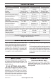
SPECIFICATIONS MODEL MNSD100HBA BTU (available) MNSD200TBA-BB MNSD300TBA-BB 10,000 Ignition Gas Type 30,000 Electric Piezo Electric Piezo Electric Piezo Using Natural Gas Using Natural Gas Using Natural Gas Pressure Regulator Setting Inlet Gas Pressure* (inches of water) Gas Type 20,000 4" W.C. 4" W.C. 4" W.C.
LOCAL CODES Install and use heater with care. Follow all local codes. In the absence of local codes, use the latest edition of The National Fuel Gas Code, ANSI Z223.1/NFPA 54*. *Available from: American National Standards Institute, Inc. 25 West 43rd Street New York, NY 10036 National Fire Protection Association, Inc. 1 Batterymarch Park Quincy, MA 02269-9101 State of Massachusetts: The installation must be made by a licensed plumber or gas fitter in the Commonwealth of Massachusetts.
WATER VAPOR: A BY-PRODUCT OF UNVENTED ROOM HEATERS Water vapor is a by-product of gas combustion. An unvented room heater produces approximately one (1) ounce (30 mL) of water for every 1,000 BTUs (0.3 KWs) of gas input per hour. Unvented room heaters are recommended as supplemental heat (a room) rather than a primary heat source (an entire house). In most supplemental heat applications, the water vapor does not create a problem.
AIR FOR COMBUSTION AND VENTILATION VENTILATION AIR Ventilation Air From Inside Building This fresh air would come from an adjoining unconfined space. When ventilating to an adjoining unconfined space, you must provide two permanent openings: one within 12" of the ceiling and one within 12" of the floor on the wall connecting the two spaces (see options 1 and 2, Figure 2). You can also remove door into adjoining room (see option 3, Figure 2). Follow the National Fuel Gas Code, ANSI Z223.
INSTALLATION NOTICE: This heater is intended for use as supplemental heat. Use this heater along with your primary heating system. Do not install this heater as your primary heat source. If you have a central heating system, you may run system’s circulating blower while using heater. This will help circulate the heat throughout the house. In the event of a power outage, you can use this heater as your primary heat source.
INSTALLATION CHECK GAS TYPE FASTENING HEATER TO WALL Be sure your gas supply is right for your heater. Otherwise, call dealer where you bought the heater for proper type heater. Mounting Bracket The mounting bracket is located on back panel of heater (see Figure 5). It has been taped there for shipping. Remove mounting bracket from back panel. CLEARANCES TO COMBUSTIBLES Carefully follow the instructions below. This heater is a freestanding unit designed to be mounted on a wall or set on a base.
INSTALLATION Marking Screw Locations 1. Tape mounting bracket to wall where heater will be located. Make sure mounting bracket is level. WARNING: Maintain minimum clearances shown in Figure 4, page 10. If you can, provide greater clearances from floor and joining wall. 2. Mark screw locations on wall (see Figure 7). Note: Mark only last hole on each end of mounting bracket. Insert mounting screws through these holes only. 3. Remove tape and mounting bracket from wall. Adjoining Wall 6 3/4" Min.
Attaching to Wall Anchor Method For attaching mounting bracket to hollow walls (wall areas between studs) or solid walls (concrete or masonry): 1. Drill holes at marked locations using 5/16" drill bit. For solid walls (concrete or masonry), drill at least 1" deep. 2. Fold wall anchor as shown in Figure 8. 3. Insert wall anchor (wings first) into hole. Tap anchor flush to wall. 4. For thin walls (1/2" or less), insert red key into wall anchor. Push red key to “pop” open anchor wings (see Figure 9).
INSTALLATION INSTALLATION OF BASE STAND (If Equipped) Before installing heater to base, please make sure you have a hardware packet that contains the following items: 2 - Base Feet 4 - Sheet Metal Screws 1. Carefully lay heater on its back on a table with the bottom of the heater extending outside the table edge. 2. Attach base feet to heater using sheet metal screws. Base Feet Sheet Metal Screws Figure 12 - Installing Base Feet 200213-01B www.usaprocom.
INSTALLATION GAS SELECTION CAUTION: To avoid gas leakage for the gas not being used at the inlet of regulator, a qualified installer or service technician must use supplied cap. You will notice a color coded plunger on the inside of the regulator. This is normal. When the inlet connection fitting is inserted and tightened, this plunger will be pushed back by the fitting making all of the adjustments for the gas being supplied. DO NOT REMOVE THE PLUNGER. The regulator will not work.
INSTALLATION 2. Apply thread sealant to the threads on the connection fitting. While pushing in, rotate the fitting clockwise until the threads engage the regulator. After the fitting has been hand tightened into the regulator use a wrench to complete tightening of the fitting. Install additional fitting to connect to the house supply. Fitting supplied by installer, may vary. Use only the cap supplied on the regulator. Do not use an off the shelf pipe plug. This can damage the plunger.
INSTALLATION CONNECTING TO GAS SUPPLY WARNING: A qualified service technician must connect heater to gas supply. Follow all local codes. WARNING: This appliance requires a 3/8" NPT (National Pipe Thread) inlet connection to the pressure regulator. WARNING: For natural gas, Never connect heater to private (non-utility) gas wells. This gas is commonly known as wellhead gas. WARNING: Do not overtighten gas connections. CAUTION: Use only new, black iron or steel pipe.
INSTALLATION Apply pipe joint sealant lightly to male threads. the vent pointing down as shown in Figure This will prevent excess sealant from going 16. Pointing the vent down protects it from into pipe. Excess sealant in pipe could result freezing rain or sleet. in clogged heater valves. Install sediment trap in supply line as shown For propane/LP gas, the installer must supply in Figure 15. Place sediment trap where it is an external regulator. The external regulator within reach for cleaning.
INSTALLATION 4. Check all joints of gas supply piping system. Apply a noncorrosive leak detection fluid to all joints. If bubbles form, there may be a leak. 5. Correct all leaks at once. 6. Reconnect heater and equipment shutoff valve to gas supply. Check reconnected fittings for leaks. Test Pressures Equal To or Less Than 1/2 PSIG (3.5 kPa) 1. Close equipment shutoff valve (see Figure 17). 2.
OPERATION FOR YOUR SAFETY READ BEFORE LIGHTING WARNING: If you do not follow these instructions exactly, a fire or explosion may result causing property damage, personal injury or loss of life. A. This appliance has a pilot which must be lighted by hand. When lighting the pilot, follow these instructions exactly. B. BEFORE LIGHTING smell all around the appliance area for gas. Be sure to smell next to the floor because some gas is heavier than air and will settle on the floor.
OPERATION Note: If pilot goes out, repeat steps 3 through 7. This heater has a safety interlock system. Wait one (1) minute before lighting pilot again. 8. Turn control knob counterclockwise to desired heating level. The main burner should light. Set control knob to any heat level between 1 and 5. CAUTION: Do not try to adjust heating levels by using the equipment shutoff valve. THERMOSTAT CONTROL OPERATION The thermostatic control used on this model differs from standard thermostats.
OPERATION TO TURN OFF GAS TO APPLIANCE Shutting Off Heater 1. Turn control knob clockwise to the OFF position. 2. Turn off all electric power to the appliance if service is to be performed. Shutting off burner only (pilot stays lit) Turn control knob clockwise to the PILOT/IGN position. MANUAL LIGHTING PROCEDURE (ALL MODELS) 1. Remove lower front panel. 2. Follow steps 1 through 5 under Lighting Instructions, page 19 or 20. 3. With control knob pressed in, strike match.
ELECTRICAL CONNECTION FOR HEATERS EQUIPPED WITH A BLOWER Do not use this heater if any part of it has been under water. Immediately call a qualified service technician to inspect the fireplace and replace any part of the electrical system which has been under water. GROUNDING INSTRUCTIONS This heater is for use on 120 volts. The cord has a plug as shown at A in Figure 23. An adapter as shown at C is available for connecting three-blade grounding-type plugs to two-slot receptacles.
INSPECTING HEATER IMPORTANT: Owner’s should check pilot flame pattern and burner flame pattern often. Incorrect flame patterns indicate the need for cleaning (see Care and Maintenance, page 24) or service. WARNING: Only a qualified service person should service and repair heater. This includes maintenance requiring replacement or alteration of components. PILOT FLAME PATTERN Figure 24 shows a correct pilot flame pattern. Figure 25 shows an incorrect pilot flame pattern.
CARE AND MAINTENANCE WARNING: Turn off heater and let cool before servicing. CAUTION: You must keep control areas, burner, and circulating air passageways of heater clean. Inspect these areas of heater before each use. Have heater inspected yearly by a qualified service technician. Heater may need more frequent cleaning due to excessive lint from carpeting, bedding material, pet hair, etc. WARNING: Failure to keep the primary air opening(s) of the burner(s) clean may result in sooting and property damage.
TROUBLESHOOTING WARNING: If you smell gas: • Shut off gas supply. • Do not try to light any appliance. • Do not touch any electrical switch; do not use any phone in your building. • Immediately call your gas supplier from a neighbor’s phone. Follow the gas supplier’s instructions. • If you cannot reach your gas supplier, call the fire department. WARNING: Only a qualified service technician should service and repair heater. Make sure that power is turned off before proceeding.
TROUBLESHOOTING Problem Possible Cause Corrective Action When ignitor button is 1. Ignitor electrode is posi- 1. Replace pilot assembly. pressed in, there is no tioned wrong. Ignitor elecspark at ODS/pilot. trode is broken. 2. Ignitor electrode is not con- 2. Replace ignitor cable. nected to ignitor cable. 3. Ignitor cable is pinched or 3. Free ignitor cable if pinched wet. by any metal or tubing. Keep ignitor cable dry. 4 Broken ignitor cable. 4. Replace ignitor cable. 5. Bad piezo ignitor. 5.
TROUBLESHOOTING Problem Possible Cause Corrective Action Burner(s) does not light 1. Burner orifice is clogged. after ODS/pilot is lit. 1. Clean burner orifice (see Care and Maintenance, page 24) or replace burner orifice. 2. Burner orifice diameter is too 2. Replace burner orifice. small. 3. Inlet gas pressure is too low. 3. Contact local gas supplier. Delayed ignition of 1. Manifold pressure is too low. 1. Contact local gas supplier. burner(s). 2. Burner orifice is clogged. 2.
TROUBLESHOOTING Problem Possible Cause Corrective Action Heater produces a click- 1. Metal is expanding while 1. This is common with most ing/ticking noise just after heating or contracting while heaters. If noise is excesburner is lit or shut off. cooling. sive, contact qualified service technician. White powder residue 1. When heated, the vapors 1. Turn heater off when using forming within burner from furniture polish, wax, furniture polish, wax, carpet box or on adjacent walls carpet cleaners, etc.
REPLACEMENT PARTS Note: Use only original replacement parts. This will protect your warranty coverage for parts replaced under warranty. PARTS UNDER WARRANTY Contact authorized dealers of this product. If they can’t supply original replacement parts, call Customer Service toll free at 1-866-573-0674 for referral information.
PARTS MODELS MNSD100HBA & MNSD100TBA 9 1 10 15 2 3 12 4 5 6 T-Stat Manual 7 14 11 8 13 30 www.usaprocom.
PARTS MODELS MNSD100HBA & MNSD100TBA This list contains replaceable parts for your heater. When ordering replacement parts, follow the instructions listed under Replacement Parts on page 29 of this manual.
PARTS MODELS MNSD200TBA & MNSD300TBA 9 1 2 11 12 3 4 5 13 10 6 14 7 8 32 www.usaprocom.
PARTS MODELS MNSD200TBA & MNSD300TBA This list contains replaceable parts for your heater. When ordering replacement parts, follow the instructions listed under Replacement Parts on page 29 of this manual.
PARTS MODELS MNSD200TBA-BB & MNSD300TBA-BB 9 1 2 11 12 3 4 5 13 10 6 14 7 15 16 8 34 www.usaprocom.
PARTS MODELS MNSD200TBA-BB & MNSD300TBA-BB This list contains replaceable parts for your heater. When ordering replacement parts, follow the instructions listed under Replacement Parts on page 29 of this manual.
WARRANTY KEEP THIS WARRANTY Model ________________________________ Serial No. _____________________________ Date Purchased ________________________ Keep receipt for warranty verification. REGISTER YOUR PRODUCT AT WWW.USAPROCOM.COM IMPORTANT: We urge you to register your product within 10 days of date of installation, complete with entire serial number which can be found on the rating plate. Please fill out the warranty information above for your personal records. Retain this manual for future reference.
CALENTADOR DE GAS DE PARED SIN VENTILAS MANUAL DE FUNCIONAMIENTO E INSTALACIÓN DEL PROPIETARIO LLAMA AZUL MODELOS MNSD100TBA, MNSD200TBA MNSD300TBA, MNSD100HBA MNSD200TBA-BB MNSD300TBA-BB PFS ® US ADVERTENCIA: Este aparato está equipado para funcionar con gas (natural y propano). No se permite convertir más que a gas natural o gas propano.
TABLA DE CONTENIDOS Seguridad................................................. 39 Especificaciones....................................... 41 Agencia de Instalación Calificada............ 42 Características del Producto.................... 42 Normas Locales....................................... 43 Identificación del Producto....................... 43 Desempaque............................................ 44 Vapor De Agua: Un Producto Derivado de Los Calentadores de Habitación Sin Ventilación................
SEGURIDAD IMPORTANTE: Lea este manual del propietario cuidadosa y completamente antes de intentar ensamblar, operar o dar servicio a este calentador. El uso inadecuado de este calentador puede causar daños a la propiedad, lesiones graves o la muerte por quemaduras, incendio, explosión, electrocución e intoxicación con monóxido de carbono. No seguir estas instrucciones anula la garantía.
SEGURIDAD ADVERTENCIA: Este calentador alcanza temperaturas muy altas cuando el calentador está en funcionamiento. Mantenga a niños y adultos alejados de las superficies calientes para evitar quemaduras o que la ropa se encienda. El calentador permanecerá caliente durante algún tiempo después de que se ha apagado. Permita que la superficie se enfríe antes de tocarla. ADVERTENCIA: No coloque ropa ni otros materiales inflamables sobre el aparato ni cerca del mismo.
ESPECIFICACIONES MODELO BTU (disponible) MNSD100TBA 10,000 MNSD200TBA 20,000 MNSD300TBA 30,000 Encendido Piezoeléctrico Piezoeléctrico Piezoeléctrico Tipo de gas Con gas natural Con gas natural Con gas natural 4" de c.a. 4" de c.a. 4" de c.a. Presión del gas de entrada* (pulg. de agua) Máximo 9" de c.a. Máximo 9" de c.a. Máximo 9" de c.a. Mínimo 5" de c.a. Mínimo 5" de c.a. Mínimo 5" de c.a. Tipo de gas Con gas propano Con gas propano Con gas propano 9" de c.a. 9" de c.a.
AGENCIA DE INSTALACIÓN CALIFICADA La instalación y el remplazo de tuberías de gas, de equipos o de accesorios para la utilización de gas y la reparación y el mantenimiento de los equipos deben estar a cargo sólo de una agencia calificada.
NORMAS LOCALES Instale y use el calentador con cuidado. Siga todas las normas locales. A falta de normas locales, utilice la última edición del Código Nacional de Gas Combustible, ANSI Z223.1/NFPA 54*. *Disponible en: American National Standards Institute. Inc. 25 West 43rd Street New York, NY 10036, EE.UU. National Fire Protection Association, Inc. Batterymarch Park Quincy, MA 02269, EE.UU.
DESEMPAQUE 1. Saque el calentador de la caja. 2. Retire todo el empaque de protección que se agregó al calentador para su envío. 3. Revise el calentador para ver si hay algún daño debido al transporte. Si el calentador está dañado, informe de inmediato al distribuidor donde lo compró. VAPOR DE AGUA: UN PRODUCTO DERIVADO DE LOS CALENTADORES DE HABITACIÓN SIN VENTILACIÓN l vapor de agua es un producto derivado E de la combustión del gas.
AIRE PARA COMBUSTIÓN Y VENTILACIÓN ADVERTENCIA: Si la zona en la que la estufa se puede operar no cumple con el volumen requerido de aire de combustión en interiores , combustión y de ventilación serán facilitados por uno de los métodos descritos en el Código Nacional de Gas Combustible, ANSI Z223.1/NFPA 54, el Fuel Gas Code Internacional o con los códigos locales aplicables.
INSTALACIÓN AVISO: Este calentador está diseñado para utilizarse como calefacción adicional. Use este calentador junto con su sistema de calefacción principal. No instale este calentador como fuente de calefacción principal. Si tiene un sistema de calefacción central, puede activar el ventilador de circulación del sistema mientras utiliza el calentador. Esto ayudará a que el calor circule por toda la casa.
INSTALACIÓN DISTANCIA DE SEPARACIÓN DE COMBUSTIBLES Siga con atención las siguientes instrucciones. Este calentador es una unidad de montaje en la pared diseñada para apoyarse directamente sobre el suelo o una base de repisa. ADVERTENCIA: Mantenga las distancias mínimas como se muestra en la Figura 4. Si es posible, proporcione distancias mayores respecto al suelo, al techo y a las paredes adyacentes. Mida desde el punto más alejado del calentador. TECHO 15.
INSTALACIÓN Cómo marcar las ubicaciones de los tornillos 1. Fije el soporte de montaje a la pared con cinta, en el lugar donde estará situado. Asegúrese de que el soporte de montaje esté nivelado. ADVERTENCIA: mantenga las distancias mínimas que se muestran en la figura 4, página 47. Si puede, proporcione distancias mínimas mayores con respecto al piso y la pared de unión. 2. Marque la ubicación de los tornillos en la pared (consulte la figura 7).
INSTALACIÓN Método de fijación a viga de pared Para fijar el soporte de montaje a las vigas de pared: 1. Perfore orificios en los lugares marcados utilizando una broca de 9/64". 2. Coloque el soporte de montaje en la pared. Alinee el último orificio de cada extremo del soporte con los orificios que perforó en la pared. 3. Inserte los tornillos de montaje en el soporte y en las vigas de pared. 4. Apriete los tornillos hasta que el soporte de montaje esté asegurado firmemente a las vigas de pared.
INSTALACIÓN 1. 2. 3. 4. 5. 6. 7. 8. Instalación de los tornillos de montaje inferiores Instale el soporte base en la parte inferior del calentador con dos tornillos. Puede ser más cómodo retirar el calentador del soporte de pared para la colocación. Coloque el calentador sobre el soporte de montaje de pared. Marque la ubicación de los tornillos en la pared. Quite el calentador del soporte de montaje.
INSTALACIÓN SELECCIÓN DE GAS LPG PRECAUCIÓN: Dos instalaciones de líneas de gas, al mismo tiempo están prohibidos. INLET GAS PRESSURE MAX 1/2 PSIG (3.5 KPA) NG Este aparato viene ajustado de fábrica para gas propano/ LP. No se requieren cambios para la conexión a propano/ LP. Sólo un instalador o técnico de servicio calificado puede realizar la selección de gas y la conexión al suministro de gas.
INSTALACIÓN 2. Aplique sellador de roscas a las roscas en el accesorio de conexión. Mientras presiona, gire hacia la derecha el ajuste hasta que las roscas se acoplan al regulador. Después de la instalación se ha apretado sido parte en el regulador con una llave para completar endurecimiento del accesorio. Instale accesorio adicional para conectar al suministro de la casa. Racor suministrados por el instalador, puede variar. Utilice solamente el tapón suministrado en el regulador.
INSTALACIÓN CONEXIÓN AL SUMINISTRO DE GAS ADVERTENCIA: Una persona de servicio capacitada debe conectar el calentador al suministro de gas. Siga todas las normas locales. ADVERTENCIA: Este aparato requiere una conexión de entrada tipo NPT (rosca de tubería nacional) de 3/8" al regulador de presión. ADVERTENCIA: Para gas natural, nunca conecte el calentador a pozos de gas privados (que no sean de servicio público). Este gas se conoce comúnmente como gas de pozo.
INSTALACIÓN Antes de instalar el calentador, asegúrese de tener los elementos que se indican a continuación.
INSTALACIÓN REVISIÓN DE LAS CONEXIONES DE GAS ADVERTENCIA: Después de instalar el calentador o de darle servicio, pruebe todas las conexiones y tubos de gas de la unidad, tanto internas como externas, en busca de fugas. Repare todas las fugas inmediatamente. ADVERTENCIA: Nunca use una llama al descubierto para verificar si hay fugas. Aplique líquido no corrosivo para detectar fugas en todas las uniones. La formación de burbujas indicará una fuga. Repare todas las fugas inmediatamente.
INSTALACIÓN Comprobación de la presión de las conexiones de gas del calentador 1. Abra la válvula de cierre del equipo (consulte la figura 17, página 55). 2. Si usa gas natural, abra la válvula principal de gas ubicada en el medidor de gas o cerca de éste. Si usa propano o gas LP, abra la válvula de suministro de propano o gas LP. 3. Compruebe que la perilla de control del calentador esté en la posición OFF (apagado). 4.
FUNCIONAMIENTO POR SU SEGURIDAD, LEA ESTO ANTES DE ENCENDER EL CALENTADOR ADVERTENCIA: No seguir estas instrucciones al pie de la letra puede resultar en incendio o explosión que produzcan daños a la propiedad, lesiones físicas o la muerte. A. Este aparato tiene un piloto que se debe encender manualmente. Cuando encienda el piloto, siga estas instrucciones al pie de la letra. B. ANTES DE ENCENDERLO compruebe que alrededor del aparato no hay olor a gas.
FUNCIONAMIENTO • Si al soltar la perilla de control ésta no regresa a su posición original, llame a un técnico de servicio calificado o a su proveedor de gas para que realicen las reparaciones necesarias. 6. Continúe presionando la perilla de control y, al mismo tiempo, oprima y suelte el botón de encendido. Esto encenderá el piloto. El piloto está instalado en la parte anterior del quemador.
FUNCIONAMIENTO 5. Gire la perilla de control en el sentido contrario a las agujas del reloj hacia la posición PILOT/IGN (PILOTO). Presione la perilla de control durante cinco (5) segundos. Nota: la primera vez que haga funcionar el calentador después de conectar el suministro de gas, la perilla de control se debe presionar durante aproximadamente treinta (30) segundos. Esto permitirá purgar el aire del sistema de suministro de gas. 6.
CONEXIÓN ELÉCTRICA PARA CALENTADORES EQUIPADO CON UN VENTILADOR No utilice este calentador si alguna de sus piezas estuvo sumergida en agua. Llame de inmediato a un técnico en mantenimiento calificado a fin de que inspeccione la chimenea y remplace cualquier pieza del sistema eléctrico que haya estado bajo agua. INSTRUCCIONES DE CONEXIÓN A TIERRA Este calentador fue diseñado para su uso con 120 voltios. El cable tiene un enchufe, como se muestra en la Figura 23.
CABLEADO ELÉCTRICO Todo nuevo cableado eléctrico del electrodoméstico debe realizarlo un electricista calificado. Este cableado se debe realizar de acuerdo con los códigos locales y/o, en Canadá, de acuerdo con el Código de Electricidad de Canadá CSA C22.1 actual, y para las instalaciones en EE.UU., de acuerdo con el Código Nacional de Electricidad, ANSI/ NFPA No. 70.
INSPECCIÓN DEL CALENTADOR IMPORTANTE: El propietario debe revisar frecuentemente los patrones de la llama del piloto y de la llama del quemador. Patrones de llama incorrectos indican la necesidad de limpieza o servicio de mantenimiento (consulte Cuidado y mantenimiento, página 63). ADVERTENCIA: Sólo una persona de servicio capacitada debe repararlo o darle servicio. Esto incluye el mantenimiento requerido, refacciones o alteración de componentes.
CUIDADO Y MANTENIMIENTO ADVERTENCIA: Apague el calentador y deje que se enfríe antes de darle mantenimiento. PRECAUCIÓN: Debe mantener limpias las áreas de control, el quemador y las vias de circulación de aire del calentador. Inspeccione estas áreas del calentador antes de cada uso. Haga que una persona de servicio calificada inspeccione el calentador una vez al año.
SOLUCIÓN DE PROBLEMAS ADVERTENCIA: Si percibe olor a gas • Cierre el suministro de gas. • No intente encender ningún aparato. • No toque ningún interruptor eléctrico; no use ningún teléfono en el edificio. • Llame inmediatamente a su proveedor de gas desde el teléfono de algún vecino. Siga las instrucciones del proveedor de gas. • Si no puede localizar al proveedor de gas, llame al departamento de bomberos. ADVERTENCIA: Sólo una persona de servicio capacitada debe reparar la calentador y darle servicio.
SOLUCIÓN DE PROBLEMAS Problema Causa Posible Acción correctiva Cuando se presiona el 1. Electrodo de encendido 1. Remplace el electrodo del botón del encendedor, no está mal colocado. Electroencendedor. hay chispa en el piloto/ do de encendido está roto. ODS. 2. El electrodo del encende- 2. Remplace el cable del encendor no está conectado al dedor. cable del encendedor. 3. El cable del encendedor 3. Libere el cable del encendedor está comprimido o mojado. si algún metal o tubería lo está comprimiendo.
SOLUCIÓN DE PROBLEMAS Problema Causa Posible Acción correctiva El piloto/ODS se en- 1. La perilla de control no está 1. Presione la perilla de control ciende pero la llama se presionada completamente. completamente. extingue cuando la perilla 2. La perilla de control no se 2. Después de que el piloto/ODS de control se suelta. presionó durante el tiempo se encienda, mantenga la suficiente. perilla de control presionada durante 30 segundos. 3. La válvula de cierre del 3.
SOLUCIÓN DE PROBLEMAS Problema Causa Posible Acción correctiva Llamas amarillas alta 1. No hay suficiente aire. durante la combustión en el quemador. 1. Revise el quemador en busca de polvo y residuos. Si los hay, limpie el quemador (consulte Cuidado y mantenimiento, en la página 63). 2. El regulador de gas está 2. Remplace el regulador de gas. defectuoso. 3. La entrada de la presión de 3. Contacte a su proveedor local gas es demasiado baja. de gas. Hay olor a gas durante la 1.
SOLUCIÓN DE PROBLEMAS Problema Causa Posible El calentador produce olores no deseados. Acción correctiva 1. En el calentador se están 1. Abra la ventana para ventilar quemado vapores provela habitación. Deje de utilizar nientes de pintura, fijador los productos que ocasionan para el cabello, pegamenel olor mientras el calentador tos, productos de limpieza, esté funcionando. productos químicos, alfombras nuevas, etc. (Consulte la nota IMPORTANTE pagina 64). 2. Fugas de gas. Consulte la 2.
PIEZAS DE REPUESTO Nota: use sólo piezas de repuesto originales. Esto protegerá la cobertura de su garantía para partes remplazadas bajo la garantía. PIEZAS CON GARANTÍA Comuníquese con los distribuidores autoriza- • los números de modelo y de serie de su dos de este producto.
PIEZAS MODELOS MNSD100HBA Y MNSD100TBA 9 1 10 15 2 3 12 4 5 6 T-Stat Manual 7 14 11 8 13 70 www.usaprocom.
PIEZAS MODELOS MNSD100HBA Y MNSD100TBA Esta lista contiene las piezas remplazables utilizadas en el calentador. Al hacer un pedido de piezas, siga las instrucciones listadas en Piezas de repuesto en la página 69 de este manual.
PIEZAS MODELOS MNSD200TBA Y MNSD300TBA 9 1 2 11 12 3 4 5 13 10 6 14 7 8 72 www.usaprocom.
PIEZAS MODELOS MNSD200TBA Y MNSD300TBA Esta lista contiene las piezas remplazables utilizadas en el calentador. Al hacer un pedido de piezas, siga las instrucciones listadas en Piezas de repuesto en la página 69 de este manual.
PIEZAS MODELOS MNSD200TBA-BB Y MNSD300TBA-BB 9 1 2 11 12 3 4 5 13 10 6 14 7 15 16 8 74 www.usaprocom.
PIEZAS MODELOS MNSD200TBA-BB Y MNSD300TBA-BB Esta lista contiene las piezas remplazables utilizadas en el calentador. Al hacer un pedido de piezas, siga las instrucciones listadas en Piezas de repuesto en la página 69 de este manual.
GARANTÍA GUARDE ESTA GARANTÍA Modelo___________________________________ Número de serie___________________________ Fecha de compra __________________________ Conserve su recibo para la verificación de la garantía. REGISTRE SU PRODUCTO EN WWW.USAPROCOM.COM IMPORTANTE: Le pedimos que registre su producto dentro de los 10 días de la fecha de instalación, lleve a cabo con el número de serie completa que se puede encontrar en la placa de características.