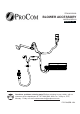
ITEM #0293809 BLOWER ACCESSORY MODEL #QEB100 Español p. 35 Questions, problems, missing parts? Before returning to your retailer, call our customer service department at 1-877-886-5989, 8:00 a.m - 4:30 p.m., EST, Monday - Friday or e-mail customerservice@usaprocom.com.
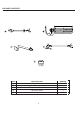
PACKAGE CONTENTS A B D C E PART A B C D E DESCRIPTION Power Cord Blower Temperature Sensor Connector Wires Rocker Switch 2 Quantity 1 1 1 1 1
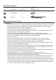
HARDWARE CONTENTS Part Description Picture (Shown to size) Quantity AA M4.2X8 Screw 10 BB Cable Tie 2 Not shown to size WARNINGS AND CAUTIONS WARNING • Read all instructions and warnings carefully before starting installation. Failure to follow these instructions may result in a possible electric shock, fire hazard and will void the warranty. • Read all instructions before using this appliance. • If possible always unplug this appliance when not in use.
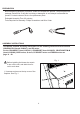
PREPARATION Before beginning assembly of product, make sure all parts are present. Compare parts with package contents list. If any part is missing or damaged, do not attempt to assemble the product. Contact customer service for replacement parts. Estimated Assembly Time: 60 minutes Tools Required for Assembly: Philips Screwdriver and Wire Cutter ASSEMBLY INSTRUCTIONS This blower contains assembly instructions for the following models and item numbers CRHED200TA3 (Item # 0328247), and ED series.
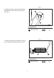
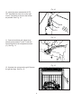
Fig. 2 2. Attach the power cord (A) to the fireplace with M4.2X8 screws (AA) on the top cover. See Fig. 2. AA A Hardware Used AA M4.2X8 screw x3 Fig. 3 3. Attach the blower (B) assembly to the top cover with M4.2X8 screws (AA). See Fig. 3. B AA Hardware Used AA 5 M4.
Fig. 4 4. Attach the grounding port to shell board with M4.2X8 screw (AA); refer to grounding label. Be sure to insert the gasket between the shell board and the grounding port. See Fig. 4. AA Hardware Used AA M4.2X8 screw x1 Fig. 5 5. Insert the blower connector (male port) into the connector (female port) to protecting jacket in the fireplace. See Fig. 5.
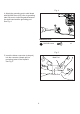
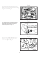
Fig. 6 6. Insert the male port, which is on the black power supply wire (marked P2), into the corresponding female port (marked P2). See Fig. 6. Fig. 7 7. Insert the female port, which is on the white power supply wire (marked P1), into the corresponding male port (marked P1). See Fig. 7.
Fig. 8 8. IMPORTANT: Bundle the wiring to the top board with the cable tie (BB). This is to avoid any heat damage to the insulation board. See Fig. 8. BB Hardware Used BB Cable Tie x1 Fig. 9 9. Attach temperature sensor (C) to the back of the firebox with M4.2X8 screws (AA). See Fig. 9. C AA Hardware Used AA 8 M4.
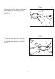
Fig. 10 10. Insert the wires marked with AUTO, OFF and MAN into wire slot on the right corner. Feed them as close to the bottom as possible. See Fig. 10. MAN OFF AUTO Fig. 11 11. Connect two black and yellow wires (female ports) maked T1 and T2 with the two male ports on the temperature sensor (C). See Fig. 11. T1 C Fig. 12 12. Unscrew two screws on the grill. Remove the grill and logs. See Fig. 12.
Fig. 13 13. Unscrew the control panel (two screws). Pull the control panel out without disconnecting the ignitor wire. See Fig. 13. Fig. 14 14. Feed the AUTO, OFF, MAN connectors through the rocker switch hole on the left of the control panel. See Fig. 14. IGNITOR Fig. 15 15. Connect the AUTO, OFF, MAN wires to the three corresponding male tabs on the rocker switch (E). See Fig. 15.
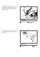
Fig. 16 16. Push the rocker switch (E) into the control panel. See Fig. 16. E Fig. 17 17. Re-attach the control panel with the two screws taken off in step 13. See Fig. 17. Fig. 18 18. Lay the logs according to the original layout. Refer to manual for log layout. See Fig. 18.
Fig. 19 19. Re-attach the grill with the two screws taken off in step 12. See Fig. 19. Fig. 20 20. Re-attach the top panel with the screws taken off in step 1. See Fig. 20. Fig. 21 21. Push the protection tab in to make it embed into the surface of top cover.
Installation blower assembly position Install temperature sensor Install wire and grounding Install blower Install rocker switch 13
Instruction for the models CRHQD250T (Item # 0293811), CRHSD25RT (Item # 0328253), CRHFD400RT-M-M (Item # 0328248), BD23 series, Q stove, PCSD25RT series and FBD400 series. Fig. 1 Before installing the blower, be certain to turn off the unit, and allow time for unit to cool down. 1. Unscrew and remove the blower access panel. See Fig. 1. Fig. 2 2. Attach blower (B) onto the blower access panel with M4.2X8 screws (AA). See Fig. 2. B AA Hardware Used AA 14 M4.
Fig. 3 3. Attach the power cord (A) to the blower access panel with M4.2X8 screws (AA). See Fig. 3. AA A Hardware Used AA M4.2X8 screw x3 Fig. 4 4. Attach the temperature sensor (C) to the back of the firebox with M4.2X8 screws (AA). See Fig. 4. C AA Hardware Used AA 15 M4.
Fig. 5a 5. Insert the wires marked with AUTO, OFF and MAN into wire slot on the right corner. Feed them as close to the bottom as possible. See Fig. 5a and 5b (top view) Fig. 5c (top view) (For Model # PCSD25RT only). Fig. 5b Fig.
Fig. 6 6. Connect two black and yellow wires (female ports) marked T1 and T2 with the two male ports on the temperature sensor (C). See Fig 6. T1 T2 C Fig. 7 7. Insert the female port, which is on the white power supply wire (marked P1), into the corresponding male port (marked P1). See Fig. 7. P1 Fig. 8 8. Insert the male port, which is on the black power supply wire (marked P2), into the corresponding female port (marked P2). See Fig. 8.
Fig. 9 9. Insert the blower connector (male port) into the connector (female port) to protecting jacket in the fireplace. See Fig. 9. Male Male Port port Female port Port Fig. 10 10. Attach the grounding port to the tab on the right side of the blower access hole with M4.2X8 screws (AA). See Fig. 10. Grounding Tab Tab AA Hardware Used AA M4.2X8 screw x1 Fig. 11 11. Push the grounding tab inwards (approximately 60 degrees). See Fig. 11.
Fig. 12 12. Bundle the wiring with the cable tie (BB). See Fig. 12. For Model # CRHQD250T (Item # 0293811), and Q stove only. BB Fixed Hole Hardware Used BB Cable Tie x1 Fig. 13 13. Bundle the wiring with the cable tie (BB). See Fig. 13. For Model # CRHSD25RT (Item # 0328253), Model # CRHFD400RT-M-M (Item # 0328248), and PCSD25RT only. Fixed Hole Hardware Used BB Cable Tie x1 Fig. 14 14. Bundle the wiring with the cable tie (BB). See Fig. 14. For Model # BD23 series only.
Fig. 15 15. Bundle the wiring with the cable tie (BB). See Fig. 15. For Model # FBD400 series only. Fixed Hole Hardware Used BB Cable Tie x1 Fig. 16 16. Unscrew two screws on the grill. Remove the grill and logs. See Fig. 16. For Model # CRHQD250T (Item # 0293811), Q stove, and BD32 series only. Fig. 17 17. Rotating handle, open the door, remove the logs. See Fig. 17.
Fig. 18 18. Rotating handle, open the door, remove the logs. See Fig. 18. For Model # PCSD25RT only. Fig. 19 19. Unscrew screws for fixing front log bracket and Control Panel. See Fig. 19. For Model # CRHQD250T (Item # 0293811), Q stove, and BD32 series only. Fig. 20 20. Unscrew the screws for fixing control panel. See Fig. 20. For Model # CRHSD25RT (Item # 0328253), and PCSD25RT only.
Fig. 21 21. Unscrew screws for fixing control panel. See Fig. 21. For Model # CRHFD400RT-M-M (Item # 0328248), and FBD400 series only. Fig. 22 22. Unscrew screws for fixing the door. See Fig. 22. For Model # BD23 series only. Fig. 23 23. Feed the AUTO, OFF, MAN connectors through the rocker switch hole on the left of the control panel. See Fig. 23. For Model # CRHQD250T (Item # 0293811), Q stove, and BD32 series only.
Fig. 24 24. Feed the AUTO, OFF, MAN connectors through the rocker switch hole on the left of the control panel. See Fig. 24. For Model # CRHSD25RT (Item # 0328253), CRHFD400RT-M-M (Item # 0328248), PCSD25RT, and FBD400 series only. Fig. 25 25. Connect the AUTO, OFF, MAN wires to the threee corresponding male tabs on the rocker switch (E). See Fig. 25. AUTO E Fig. 26 26. Push the rocker switch (E) into the control panel. See Fig. 26. For Model # CRHQD250T (Item # 0293811), Q stove, and BD32 series only.
Fig. 27 27. Push the rocker switch (E) into the control panel. See Fig. 27. For Model # CRHSD25RT (Item # 0328253), CRHFD400RT-M-M (Item # 0328248), PCSD25RT, and FBD400 series only. E Fig. 28 28. Re-attach the control panel with the two screws taken off in step 16. See Fig. 28. For Model # CRHQD250T (Item # 0293811), Q stove, and BD32 series only. Fig. 29 29. Re-fix Control Panel. See Fig. 29. For Model # CRHSD25RT (Item # 0328253), and PCSD25RT only.
Fig. 30 30. Re-fix Control Panel. See Fig. 30. For Model # CRHFD400RT-M-M (Item # 0328248), and FBD400 series only. Fig. 31 31. Lay the logs according to the original layout. Refer to manual for log layout. See Fig. 31. For Model # CRHQD250T (Item # 0293811), Q stove and BD32 series only. Fig. 32 32. Lay back the logs according to the original layout, and shut the door. See Fig. 32. For Model # CRHFD400RT-M-M (Item # 0328248), and FBD400 series only.
Fig. 33 33. Lay back the logs according to the original layout, and shut the door. See Fig. 33. For Model # CRHSD25RT (Item # 0328253) only. Fig. 34 34. Lay back the logs according to the original layout, and shut the door. See Fig. 34. For Model # PCSD25RT only. Fig. 35 35. Check all the wires, then re-attach blower access panel to the fireplace. See Fig.
Installation blower assembly position For Model # CRHQD250T (Item # 0293811), and Q stove.
Installation blower assembly position For Model BD23 series Install temperature sensor Install wire and grounding Install blower Install rocker switch 28
Installation blower assembly position For Model # CRHSD25RT (Item # 0328253), and PCSD25RT.
ELECTRICAL CONNECTION A 15 amp, 120 Volt, 60 Hz circuit with a properly grounded outlet is required. Preferably, the fireplace will be on a dedicated circuit as other appliances on the same circuit may cause the circuit breaker to trip or the fuse to blow when the heater is in operation. Plan the installation to avoid the use of an extension cord. Extension cords are for temporary use only.
ELECTRICAL WIRING DIAGRAM Any electrical re-wiring of this appliance must be done by a qualified electrician. This wiring must be done in accordance with local codes and/or in Canada with the current CSA C22.1 Canadian Electrical Code, and for US installations, the National Electrical Code ANSI/NFPA NO 70. If repairing or replacing any electrical component or wiring, the original wire routing, color coding and securing locations must be followed. WHITE GREEN BLACK BLACK 1. Power Cord 2.
REPLACEMENT PARTS NOTE: Use only original replacement parts. This will protect your warranty coverage for parts replaced under warranty. PARTS UNDER WARRANTY Call Customer Service toll free at (1-877-886-5989) for referral information.
REPLACEMENT PARTS LIST For replacement parts, call our customer service department at 1-877-886-5989, 8:00 a.m - 4:30 p.m., EST, Monday - Friday or e-mail customerservice@usaprocom.com.
WARRANTY INFORMATION Keep This Warranty IMPORTANT: We urge you to fill your warranty registration card within TEN(10) days of date of installation, complete with the entire serial number which can be found on the rating plate. Retain this portion of the card for your record. Always specify model and serial numbers when communicating with customer service. We reserve the right to amend these specifications at any time without notice. The only warranty applicable is our standard written warranty.