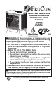
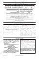
VENT-FREE GAS STOVE OWNER’S OPERATION AND INSTALLATION MANUAL MODELS PCSD25T PCSD25RT PFS ® US WARNING: If the information in this manual is not followed exactly, a fire or explosion may result causing property damage, personal injury or loss of life. — Do not store or use gasoline or other flammable vapors and liquids in the v icinity of this or any other appliance. — WHAT TO DO IF YOU SMELL GAS • Do not try to light any appliance.
TABLE OF CONTENTS Safety......................................................... 3 Qualified Installing Agency......................... 4 Specifications............................................. 5 Product Features........................................ 5 Local Codes............................................... 5 Product Identification.................................. 6 Unpacking.................................................. 6 Water Vapor: A By-Product Of Unvented Room Heaters....................
SAFETY IMPORTANT: Read this owner’s manual carefully and completely before trying to assemble, operate, or service this heater. Improper use of this heater can cause serious injury or death from burns, fire, explosion, electrical shock and carbon monoxide poisoning. Failure to follow these instructions will void the warranty. Only a qualified installer, service agent, or local gas supplier may install and service this product.
SAFETY 1. Do not place Propane/LP supply tank(s) inside any structure. Propane/LP supply tank(s) must be placed outdoors. 2. This heater shall not be installed in a bedroom or bathroom. 3. This heater needs fresh air ventilation to run properly. This heater has an Oxygen Depletion Sensing (ODS) safety shutoff system. The ODS shuts down the heater if not enough fresh air is available. See Air for Combustion and Ventilation, pages 7 through 9. If heater keeps shutting off, see Troubleshooting, page 26. 4.
SPECIFICATIONS Model PCSD25T Input Rating, Max. 23,000 Btu/Hr 23,000 Btu/Hr Input Rating, Min. 14,000 Btu/Hr 19,000 Btu/Hr Model Gas Type PCSD25RT 23,000 Btu/Hr 23,000 Btu/Hr N/A Ignition Electronic Piezo Pressure Regulator Setting Inlet Gas Pressure* (inches of water) (*for purposes of input adjustment) N/A PCSD25T, PCSD25RT Natural Gas Propane Gas Electronic Piezo 4" W.C. 9" W.C. Maximum 10.5" Maximum 14" Minimum 5" Minimum 11" Heater Dimensions (HxWxD) • 28.31" × 25.
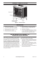
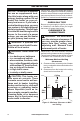
PRODUCT IDENTIFICATION Screen Logs Heater Controls (Inside Panel) Figure 1 - Vent-Free Stove UNPACKING 1. 2. 3. 4. 5. Remove top inner pack. Tilt carton so that heater is upright. Remove protective side packaging. Slide heater out of carton. Remove protective plastic wrap. 6. 7. 8. 9. Hold the screen, lift, and pull forward. Remove log set by cutting plastic ties. Carefully unwrap log. Check for any shipping damage. If heater or log is damaged, promptly inform your dealer where you bought the heater.
AIR FOR COMBUSTION AND VENTILATION WARNING: This heater shall not be installed in a confined space or unusually tight construction unless provisions are provided for adequate combustion and ventilation air. Read the following instructions to insure proper fresh air for this and other fuel-burning appliances in your home. Today’s homes are built more energy efficient than ever. New materials, increased insulation and new construction methods help reduce heat loss in homes.
AIR FOR COMBUSTION AND VENTILATION DETERMINING FRESH-AIR FLOW FOR HEATER LOCATION Determining if You Have a Confined or Unconfined Space Use this work sheet to determine if you have 4. Compare the maximum Btu/Hr the space a confined or unconfined space. can support with the actual amount of Btu/ Hr used.
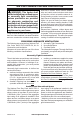
AIR FOR COMBUSTION AND VENTILATION VENTILATION AIR Ventilation Air From Inside Building This fresh air would come from an adjoining unconfined space. When ventilating to an adjoining unconfined space, you must provide two permanent openings: one within 12" of the ceiling and one within 12" of the floor on the wall connecting the two spaces (see options 1 and 2, Figure 2). You can also remove door into adjoining room (see option 3, Figure 2). Follow the National Fuel Gas Code, ANSI Z223.
INSTALLATION NOTICE: This heater is intended for use as supplemental heat. Use this heater along with your primary heating system. Do not install this heater as your primary heat source. If you have a central heating system, you may run system’s circulating blower while using heater. This will help circulate the heat throughout the house. In the event of a power outage, you can use this heater as your primary heat source. WARNING: A qualified service person must install heater. Follow all local codes.
INSTALLATION GAS SELECTION This appliance is factory preset for propane/LP gas. No changes are required for connecting to propane/LP. Only a qualified installer or service technician can perform gas selection and connecting to gas supply. CAUTION: Two gas line installations at the same time are prohibited. The access plate to the simple switching means shall not be opened while the heater is in operation.
INSTALLATION CONNECTING TO GAS SUPPLY WARNING: A qualified service technician must connect heater to gas supply. Follow all local codes. WARNING: This appliance requires a 3/8" NPT (National Pipe Thread) inlet connection to the pressure regulator. WARNING: For natural gas, Never connect heater to private (non-utility) gas wells. This gas is commonly known as wellhead gas. CAUTION: For propane/LP gas, never connect heater directly to the gas supply. This heater requires an external regulator (not supplied).
INSTALLATION For propane/LP installations, apply pipe joint sealant lightly to male threads. This will prevent excess sealant from going into pipe. Excess sealant in pipe could result in clogged heater valves. The installer must supply an external regulator. The external regulator will reduce incoming gas pressure. You must reduce incoming gas pressure to between 11" and 14" of w.c. If you do not reduce incoming gas pressure, heater regulator damage could occur.
INSTALLATION CHECKING GAS CONNECTIONS WARNING: Test all gas piping and connections for leaks after installing or servicing. Correct all leaks at once. WARNING: Never use an open flame to check for a leak. Apply a noncorrosive leak detection fluid to all joints. If bubbles form, there is a leak. Correct all leaks at once. PRESSURE TESTING GAS SUPPLY PIPING SYSTEM Test Pressures In Excess Of 1/2 PSIG (3.5 kPa) 1.
INSTALLATION PRESSURE TESTING HEATER GAS CONNECTIONS 1. Open equipment shutoff valve (see Figure 12, page 14). Apply a noncorrosive leak 10, page 14). detection fluid to all joints. Bubbles forming show a leak. 2. Open main gas valve located on or near gas meter for natural gas or open pro- 5. Correct all leaks at once. pane/LP supply tank valve. 6. Light heater (see Lighting Instructions on 3. Make sure control knob of heater is in the page 18 or 19). Check all other internal OFF position.
INSTALLATION INSTALLING LOGS WARNING: Failure to position the parts in accordance with these diagrams or failure to use only parts specifically approved with this heater may result in property damage or personal injury. CAUTION: After installation, and periodically thereafter, check to ensure that no flame comes in contact with any log. With the heater set to high, check to see if flames contact any log. If so, reposition logs according to the log installation instructions in this manual.
INSTALLATION Hole for Log #5 Hole for Log #7 Log #5 Log #8 Log #4 Figure 16 - Logs #4 and #8 Log #6 Log #7 Figure 17 - Logs #5, #6 and #7 OPERATION FOR YOUR SAFETY READ BEFORE LIGHTING WARNING: If you do not follow these instructions exactly, a fire or explosion may result causing property damage, personal injury or loss of life. A. This appliance has a pilot which must be lighted by hand. When lighting the pilot, follow these instructions exactly. B.
OPERATION MODEL PCSD25T LIGHTING INSTRUCTIONS WARNING: You must operate this heater with the door closed and in the locked position. Make sure screen is installed before running heater. NOTICE: During initial operation of new heater, burning logs will give off a paper-burning smell. Orange flame will also be present. Open damper or window to vent smell. This will only last a few hours. 1. STOP! Read the safety information above. 2. Make sure equipment shutoff valve is fully open. 3.
OPERATION THERMOSTAT CONTROL OPERATION The thermostatic control used on this model differs from standard thermostats. Standard thermostats simply turn the burner on and off. The thermostat used on this heater senses the room temperature. At times the room may exceed the set temperature. If so, the burner will shut off. The burner will cycle back on when room temperature drops below the set temperature. The control knob can be set to any comfort level between Low (1) and HIGH (5).
OPERATION Note: The first time that the heater is operated after connecting the gas supply, the control knob should be pressed for about thirty (30) seconds. This will allow air to bleed from the gas system. If pilot does not stay lit, refer to Troubleshooting, pages 26 though 28. Also contact a qualified service technician or gas supplier for repairs. Until repairs are made, light pilot with match.
OPERATION REMOTE CONTROL SYSTEM AA AA AA AA Install Batteries Batteries are required in both the Remote Control (Transmitter) (2 AAA size) and Receiver (4 AA size) (see Figure 20). Note: Be sure batteries are placed correctly. Reversing the batteries can cause damage to the receiver and remote. Replace all batteries on a yearly basis or sooner. F N AR LE TE OF MO ON RE A AA Programming the Remote and Receiver The remote and receiver must be “learned” to one another. 1.
OPERATION LCD Liquid Crystal Display 1. DISPLAY Indicates CURRENT room temperature. 2. °F or °C Indicates degrees Fahrenheit or Celsius. 3. FLAME Indicates burner/valve in operation. 4. ROOM Indicates remote is in THERMO operation. 5. TEMP Appears during manual operation. 6. SET Appears during time the of setting the desired temperature in the thermo operation. OFF OPERATION Press the OFF key and the appliance flame will shut off. During this time the LCD screen will show OF (see Figure 25).
OPERATION REMOTE CONTROL The Thermo Feature on the transmitter operates the appliance whenever the ROOM TEMPERATURE varies a certain number of degrees from the SET TEMPERATURE. This variation is called the “swing” or temperature differential. The normal operating cycle of an appliance may be 4 times per hour depending on how well the room or home is insulated from the cold or drafts. The factory setting for the “swing number” is 2.
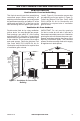
Approx. 3"-6" Above Top of Logs INSPECTING BURNERS BURNER FLAME PATTERN Figure 28 shows a correct burner flame pattern. Figure 29 shows an incorrect burner flame pattern. If burner flame pattern is incorrect as shown in Figure 29: • turn heater off (see To Turn Off Gas to Appliance, page 19 or 20). • see Troubleshooting pages 26 through 28. More Than 8" Above Top of Logs Approx.
CARE AND MAINTENANCE BURNER INJECTOR HOLDER AND PILOT AIR INLET HOLE We recommend that you clean the unit every 2,500 hours of operation or every three months. We also recommend that you keep the burner tube and pilot assembly clean and free of dust and dirt. To clean these parts we recommend using compressed air no greater than 30 PSl. Your local computer store, hardware store, or home center may carry compressed air in a can. You can use a vacuum cleaner in the blow position.
TROUBLESHOOTING WARNING: If you smell gas: • Shut off gas supply. • Do not try to light any appliance. • Do not touch any electrical switch; do not use any phone in your building. • Immediately call your gas supplier from a neighbor’s phone. Follow the gas supplier’s instructions. • If you cannot reach your gas supplier, call the fire department. WARNING: Only a qualified service technician should service and repair heater. Make sure that power is turned off before proceeding.
TROUBLESHOOTING Problem Possible Cause Corrective Action ODS/pilot lights but flame 1. Control knob is not fully 1. Press in control knob fully. goes out when control pressed in. knob is released. 2. Control knob is not pressed 2. After ODS/pilot lights, keep in long enough. control knob pressed in 30 seconds. 3. Equipment shutoff valve is 3. Fully open equipment shutoff not fully open. valve. 4. Thermocouple connection is 4. Hand tighten until snug, and loose at control valve.
TROUBLESHOOTING Problem Possible Cause Corrective Action Slight smoke or odor 1. Residues from manufactur- 1. Problem will stop after a few during initial operation. ing process. hours of operation. Heater produces a whis- 1. Turning control knob to high 1. Turn control knob to low tling noise when burner position when burner is cold. position and let warm up for is lit. a minute. 2. Air in gas line. 2. Operate burner until air is removed from line. Have gas line checked by local gas supplier. 3.
REPLACEMENT PARTS Note: Use only original replacement parts. This will protect your warranty coverage for parts replaced under warranty. PARTS UNDER WARRANTY Contact authorized dealers of this product. If they can’t supply original replacement parts, call Customer Service toll free at 1-866-573-0674 for referral information.
PARTS MODELS PCSD25T AND PCSD25RT 11 9 8 12 13 10 15 1 TEMP 5 7 3 14 LE 6 AR 2 ON RE MO TE OF F LP 4 18-1 PILO OFF T ON 17 N 16 PCSD25RT 18-5 18-2 16 PCSD25T 18-6 18-7 18-8 18-4 18-3 30 www.usaprocom.
PARTS MODELS PCSD25T AND PCSD25RT This list contains replaceable parts for your heater. When ordering replacement parts, follow the instructions listed under Replacement Parts on page 29 of this manual.
WARRANTY KEEP THIS WARRANTY Model ________________________________ Serial No. _____________________________ Date Purchased ________________________ Keep receipt for warranty verification. REGISTER YOUR PRODUCT AT WWW.USAPROCOM.COM IMPORTANT: We urge you to register your product within 10 days of date of installation, complete with entire serial number which can be found on the rating plate. Please fill out the warranty information above for your personal records. Retain this manual for future reference.