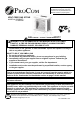
WARNING: This appliance is equipped for (Natural and Propane) gas. Field conversion is not permitted other than between natural or propane gases. VENT-FREE GAS STOVE MODEL # PCSD25T PCSD25RT CAUTION – FOR YOUR SAFETY WARNING: IF THE INFORMATION IN THIS MANUAL IS NOT FOLLOWED EXACTLY, A FIRE OR EXPLOSION MAY RESULT CAUSING PROPERTY DAMAGE, PERSONAL INJURY, OR LOSS OF LIFE. – Do not store or use gasoline or other flammable vapors and liquids in vicinity of this or any other appliance.
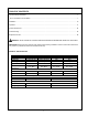
TABLE OF CONTENTS Important Safety Information ......................................................................................................................................... 3 Air For Combustion and Ventilation .............................................................................................................................. 7 Installation ....................................................................................................................................................
IMPORTANT SAFETY INFORMATION IMPORTANT: Read this owner’s manual carefully and completely before trying to assemble, operate, or service this heater. Improper use of this heater can cause serious injury or death from burns, fire, explosion, electrical shock, and carbon monoxide poisoning. Only a qualified installer, service agent, or local gas supplier may install and service this product.
7. Always run heater with control knob at PILOT/IGN, LOW or HIGH (5-1) for model PCSD25T locked positions. Never set control knob between locked positions. Poor combustion and higher levels of carbon monoxide may result. 8. Do not use heater if any part has been under water. Immediately call a qualified service technician to inspect the room heater and to replace any part of the control system and any gas control which has been under water. 9. Turn off heater and let cool before servicing.
PRODUCT FEATURES SAFETY PILOT This heater has a pilot with an Oxygen Depletion Sensing (ODS) safety shutoff system. ODS/pilot shuts off the heater if there is not enough fresh air. PIEZO IGNITION SYSTEM This heater is equipped with an electronic piezo control system. This system requires a AAA battery (provided). THERMOSTAT HEAT CONTROL (PCSD25T) The control automatically cycles the burner on and off to maintain a desired room temperature. See page 18.
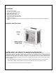
UNPACKING 1. 2. 3. 4. 5. 6. 7. 8. 9. Remove top inner pack Tilt carton so that heater is upright. Remove protective side packaging. Slide heater out of carton. Remove protective plastic wrap. Unlock door handle and pull forward. Remove log set by cutting plastic ties. Carefully un-wrap log. Check for any shipping damage. If stove or log is damaged, promptly inform your dealer where you bought the heater.
AIR FOR COMBUSTION AND VENTILATION WARNING: If the area in which the heater may be operated does not meet the required volume for indoor combustion air, combustion and ventilation air shall be provided by one of the methods described in the National Fuel Gas Code, ANSI Z223.1/NFPA 54, the International Fuel Gas Code, or applicable local codes. PRODUCING ADEQUATE VENTILATION All spaces in homes fall into one of the three following ventilation classifications: 1. Unusually Tight Construction 2.
DETERMINING FRESH-AIR FLOW FOR HEATER LOCATION Determining if You Have a Confined or Unconfined Space Use this worksheet to determine if you have a confined or unconfined space. Space: Includes the room in which you will install heater plus any adjoining rooms with doorless passageways or ventilation grills between the rooms. 1. Determine the volume of the space Length × Width × Height = cu. ft. (volume of space) Example: Space size 20 ft. (length) × 16 ft. (width) × 8 ft. (ceiling height) =2560 cu. ft.
Ventilation Air from Inside Building This fresh air would come from adjoining unconfined space. When ventilating to an adjoining unconfined space, you must provide two permanent openings: one within 12 inches of the wall connecting the two spaces ( see options 1 and 2, Figure 2). You can also remove door into adjoining room ( see option 3, Figure 2). Follow the National Fuel Gas Code NFPA 54/ANSI Z223.1. Air for Combustion and Ventilation for required size of ventilation grills or ducts.
INSTALLATION NOTICE: This heater is intended for use as supplemental heat. Use this heater along with your primary heating system. Do not install this heater as your primary heat source. If you have a central heating system, you may run system’s circulating blower while using heater. This will help circulate the heat throughout the house. WARNING: A qualified technician must install heater. Follow all local codes.
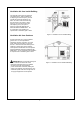
CONNECTING TO GAS SUPPLY WARNING: A qualified technician must connect heater to gas supply. Follow all local codes. WARNING: This appliance requires a 3/8 in. NPT inlet connection to pressure regulator (see Figure 5). CAUTION: Never connect heater directly to the gas supply. This heater requires an external regulator (not supplied). The external regulator between the gas supply and heater must be installed. INSTALLATION ITEMS NEEDED Before installing heater, make sure you have the items listed below.
CAUTION: Use only new black iron or steel pipe. Internally tinned copper tubing may be used in certain areas. Check your local codes. Use pipe of ½ inch diameter or greater to allow proper volume gas to heater. If pipe is too small, loss of pressure will occur. Installation must include an equipment shutoff valve, union, and plugged 1/8-inch NPT tap. Locate NPT tap within reach for test gauge hook up. NPT tap must be upstream from heater (see Figure 7).
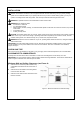
For changing from natural gas supply to propane supply 1. Remove bottom screw from cover plate, see figure 8, and rotate to expose fuel selection device. 2. For PROPANE GAS, press in knob using a flat screwdriver with a blade the width of a quarter and turn knob counterclockwise until the knob locks into the LP position (see Figure 10). Fuel selection device must be locked into either the LP position or the NG position. 3. Rotate and close cover over fuel selection device and reinstall screw. 4.
CHECKING GAS CONNECTIONS WARNING: Test all gas piping and connections for leaks after installing or servicing. Correct all leaks immediately. WARNING: Never use an open flame to check for a leak. Apply a mixture of liquid soap and water to all joints. Bubbles forming show a leak. Correct all leaks immediately. CAUTION: Make sure external regulator has been installed between gas supply and heater. See guidelines under “Connecting to Gas Supply” (page 11).
INSTALLATION Continued INSTALLING LOGS WARNING: Failure to position the parts in accordance with these diagrams or failure to use only parts included may result in property damage or personal injury. CAUTION: After installation, and periodically thereafter, check to ensure that no flame comes in contact with any log. With the heater set to high, check to see if flames contact any log. If so, reposition logs according to the log Figure 13 - Installing Log Set installation instructions in this manual.
Installation for Remote Receiver: The remote receiver operates on four AA-size batteries. It is recommended that ALKALINE batteries be used for longer battery life and maximum microprocessor performance. IMPORTANT: New or fully charged batteries are essential for proper operation of the remote receiver as the solenoid power consumption is higher than standard remote control systems. 1. 2. Take Control Box out from Control Panel.
OPERATION FOR YOUR SAFETY READ BEFORE LIGHTING WARNING: If you do not follow these instructions exactly, a fire or explosion may result causing property damage, personal injury or loss of life. NOTICE: During initial operation of new heater, burning logs will give off a paper burning smell. Orange flame will also be present. Open a window to vent smell. This will last only a few hours. CAUTION: Do not try to adjust heating levels by using the equipment shutoff valve. A.
LIGHTING INSTRUCTIONS For PCSD25T Unscrew ignitor cap and install a AAA battery with the + pointing out. Replace cap. 1. STOP! Read the safety information on page 17. 2. Warning: You must operate this heater with the door closed and in locked position. 3. Turn control knob clockwise to the OFF position, see Figure 16A. 4. Wait five (5) minutes to clear out any gas. Then smell for gas around heater and near floor. If you smell gas, STOP! Follow "B" in the safety information on Warnings plate.
TO TURN OFF GAS TO APPLIANCE Shut off heater Turn Control Knob clockwise to the OFF position. Do not force. MANUAL LIGHTING PROCEDURE (Match light) 1. Unlock and pull door handle forward to open . 2. Follow steps 1 through 5 under Lighting Instructions. 3. With Control Knob in PILOT position, strike match, and hold near pilot. Press in Control Knob; pilot should light. 4. Keep Control Knob pressed in for 30 seconds after lighting pilot. After 30 seconds, release Control Knob. 5.
LIGHTING INSTRUCTIONS For PCSD25RT 1. STOP! Read the safety information on the front and back of the warning plate on page 17. 2. Make sure manual shutoff valve is fully open. 3. Unscrew ignitor cap and install a AAA type battery with the anode (+) pointing out. Replace cap. 4. Install two (2) AAA size batteries in the remote transmitter. 5. Be sure the slide switch on the front of the receiver box is in the REMOTE position. 6. Push in the control knob slightly and turn clockwise 7.
REMOTE CONTROL FOR PCSD25RT MATCHING SECURITY CODES When matching security codes, be sure slide button on the receiver is in the REMOTE position. To program the remote receiver to LEARN a new security code, press and release the LEARN button on the top of the remote receiver, and then press ON or OFF button on the transmitter. A change in the beeping pattern at the receiver, indicates the transmitter's code has been programmed into the receiver.
OFF OPERATION Press the OFF key and the appliance flame will shut off. During this time the LCD screen will show OF (figure 23). After 3 seconds the LCD screen will default to display room temperature and the wood TEMP will show (figure 24). Figure 23 Figure 24 THERMOSTAT FUNCTION SETTING DESIRED ROOM TEMPERATURE This remote control system can control the thermostat when the transmitter is in the THERMO mode (The word ROOM must be displayed on the screen).
INSPECTING BURNERS Check pilot flame pattern and burner flame patterns often. PILOT FLAME PATTERN 1. Turn control knob to pilot position 2. Inspect pilot flame and refer to Figure 27 and 28. Figure 27 shows a correct pilot flame pattern. Figure 28 shows an incorrect pilot flame pattern. The incorrect pilot flame is not touching the thermocouple. This will cause the thermocouple to cool. When the thermocouple cools, the heater will shut down. If the pilot flame is incorrect, as shown in Figure 28.
CARE AND MAINTENANCE WARNING: Failure to keep primary air openings of burners clean may result in sooting and property damage. CAUTION: You must keep control areas, burner, and circulating air passageways of heater clean. Inspect these areas of heater before each use. Have heater inspected yearly by a qualified service person. Heater may need more frequent cleaning due to excessive lint from carpeting, bedding material, pet hair, etc.
TROUBLESHOOTING WARNING: If you smell gas Shut off gas supply. Do not try to light any appliance. Do not touch any electrical switch; do not use any phone in your building. Immediately call your gas supplier from a neighbor’s phone. Follow the gas supplier’s instructions. If you cannot reach your gas supplier, call the fire department. IMPORTANT: Operating heater where impurities in air exist may create odors.
OBSERVED PROBLEM PROBABLE CAUSE Press in control knob fully. 2. After ODS/pilot lights, keep control Equipment shutoff valve is not fully 3. Fully open equipment shutoff valve. open. 4. Hand tighten until snug, and then Control knob is not fully pressed 2. Control knob is not pressed in long 3. 4. Thermocouple connection is loose. 5. Thermocouple damaged ODS/pilot lights but flame goes out when control knob REMEDY 1. 1. in. is released. knob pressed in 30 seconds. enough.
OBSERVED PROBLEM Slight smoke or odor during PROBABLE CAUSE 1. Residues from manufacturing initial operation Heater produces a whistling process. operation. 1. Turning control knob to high (5) position when burner is cold. noise when burner is lit. 2. REMEDY 1. Problem will stop after a few hours of 1. Turn control knob to low (1) position and let warm up for a minute. 2. Operate burner until air is removed from Air in gas line. line. Have gas line checked by local propane/LP Gas Company. 3.
REPLACEMENT PARTS NOTE: Use only original replacement parts. This will protect your warranty coverage for parts replaced under warranty. PARTS UNDER WARRANTY Contact authorized dealers of this product. If they can’t supply original replacement parts, call Customer Service toll free at (1-877-886-5989) for referral information.
PARTS LIST This list contains replaceable parts used in your heater. When ordering parts, follow the instructions listed under Replacement Parts on page 28 of this manual. Key No.
WARRANTY INFORMATION Keep This Warranty IMPORTANT: We urge you to fill your warranty registration card within TEN (10) days of date of installation, complete with the entire serial number which can be found on the rating plate. Retain this portion of the card for your record. Always specify model and serial numbers when communicating with customer service. We reserve the right to amend these specifications at any time without notice. The only warranty applicable is our standard written warranty.