
Use and Care Manual

12
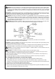
CAUTION: Use only new black iron or steel pipe. Internally tinned copper tubing may be used in certain areas.
Check your local codes. Use pipe of ½ inch diameter or greater to allow proper volume gas to heater. If pipe is
too small, loss of pressure will occur. Installation must include an equipment shutoff valve, union, and plugged
1/8-inch NPT tap. Locate NPT tap within reach for test gauge hook up. NPT tap must be upstream from heater
(see Figure 7).
IMPORTANT: Install equipment shutoff valve in an accessible location. The equipment shutoff valve is for turning on
or shutting off the gas to the appliance. Apply pipe joint sealant lightly to male threads. This will prevent excess
sealant from going into pipe. Excess sealant in pipe could result in clogged heater valves.
CAUTION: Use pipe joint sealant that is resistant to gas (PROPANE or NG). We recommend that you install a
sediment trap in a supply line as shown in Figure 7. Locate sediment trap where it is within reach for cleaning and
not likely to freeze. Install in the piping system between fuel supply and heater. A sediment trap traps moisture
and contaminants. This keeps them from going into heater controls. If sediment trap is not installed or is installed
incorrectly, heater may not run properly.
CAUTION: Avoid damage to regulator. Hold gas regulator with wrench when connecting into gas piping and/or
fittings. NG Models: 5 in. to 10.5 in. W.C. Gas supplier provide external regulator for natural gas.
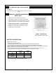
*Purchase the optional CSA design-certified equipment shut off valve from your dealer. See "Accessories".
** Minimum inlet pressure for purpose of input adjustment.
CAUTION: Two gas line installations at the same time are prohibited. The access plate to the simple switching means
shall not be opened while the heater is in operation.
This appliance can be used with propane or natural gas. It is shipped from the factory adjusted for use with propane.
Only a qualified installer or service technician can perform gas selection and connecting to gas supply.
CAUTION: To avoid gas leakage at the inlet of regulator, a qualified installer or service technician must use
metal or steel hex plug with sealant.
WARNING: Do not attempt to access or change the setting of the fuel selection means
Access to and adjustment of the fuel selection means must only be performed by a qualified service person when
connecting this appliance to a specified fuel supply at the time of installation.
Change of the selector setting to other than the fuel type specified at the time of installation could damage this ap-
pliance and render it inoperable.
The installer shall replace the access cover before completing the installation and operating this appliance.
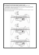
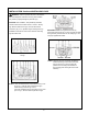
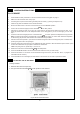
For changing from propane to natural gas supply
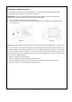
1. Remove bottom screw from cover plate, see Figure 8, and rotate to expose fuel selection device.
2. For NATURAL GAS, press in knob using a flat screwdriver with a blade the width of a quarter and turn knob
clockwise until the knob locks into the NG position (see Figure 9). Fuel selection device must be locked into the
NG position. Do not operate heater between locked positions!
3. Rotate and close cover over fuel selection device and reinstall screw.
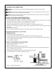
4. Remove metal or steel hex plug (with wrench provided) from natural gas inlet of regulator and install into LP inlet of
regulator, use thread sealant to assure there are no leaks.
Figure
7
–
Gas Connection