
System information


9-51
Configuring Advanced Features
Port-Based Virtual LANs (Static VLANs)
Configuring Advanced
Features
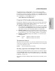
saved by not allowing packets to flood out all ports. An external router is
required to enable separate VLANs on a switch to communicate with each
other.
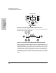
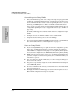
For example, referring to figure 9-39, if ports 1 through 4 belong to VLAN_1
and ports 5 through 8 belong to VLAN_2, traffic from end-node stations on
ports 2 through 4 is restricted to only VLAN_1, while traffic from ports 5
through 7 is restricted to only VLAN_2. For nodes on VLAN_1 to communicate
with VLAN_2, their traffic must go through an external router via ports 1 and 8.
Figure 9-39. Example of Routing Between VLANs via an External Router
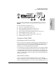
Overlapping (Tagged) VLANs. A port on the Series 2500 switches can be
a member of more than one VLAN if the device to which they are connected
complies with the 802.1Q VLAN standard. For example, a port connected to a
central server using a network interface card (NIC) that complies with the
802.1Q standard can be a member of multiple VLANs, allowing members of
multiple VLANs to use the server. Although these VLANs cannot communicate
with each other through the server, they can all access the server over the
same connection from the switch. Where VLANs overlap in this way, VLAN
“tags” are used to distinguish between traffic from different VLANs.
External
Router
VLAN_2
VLAN_1
Port 1
Port 8
Port 2
Port 3
Port 4
Port 5
Port 6
Port 7
Switch with Two
VLANs Configured