MANUALE UTENTE / INSTRUCTION MANUAL PA Combo Amplifiers ACDT180
1. PRECAUZIONI D’USO AVVERTENZA:Per ridurre il rischio di folgorazione, non rimuovere il coperchio (o il pannello posteriore). All’interno non sono contenute parti riparabili dall’utente; affidare la riparazione a personale qualificato. ATTENZIONE: Per ridurre il rischio d’incendio o di folgorazione, non esporre questo apparecchio alla pioggia o all’umidità.
Le note precedute dal simbolo contengono importanti informazioni sulla sicurezza: leggerle con particolare attenzione. ISTRUZIONI DI SICUREZZA IN DETTAGLIO. Acqua ed umidità: L’apparecchio non deve essere utilizzato in prossimità di acqua (per es. vicino a vasche da bagno, lavelli da cucina, in prossimità di piscine ecc.). Ventilazione: L’apparecchio deve essere posto in modo tale che la sua collocazione o posizione non interferisca con l’adeguata ventilazione.
Ingresso di liquidi o oggetti: Si deve prestare attenzione che non cadano oggetti e non si versino liquidi nel corpo dell’apparecchio attraverso le griglie. Uso sicuro della linea d’alimentazione: • Quando si scollega l’apparato alla rete tenere saldamente sia la spina che la presa.
• Avvitare completamente i terminali a vite degli altoparlanti per garantire la sicurezza dei contatti. • Per ragioni di sicurezza, non annullare il collegamento a massa della spina. Il collegamento a massa è necessario per salvaguardare la sicurezza dell’operatore Utilizzare unicamente i connettori e gi accessori specificati dal produttore.
Grazie per aver scelto un prodotto Proel e della fiducia riposta nel nostro marchio, sinonimo di professionalità, accuratezza, elevata qualità ed affidabilità. Tutti i nostri prodotti sono conformi alle normative CE per utilizzazione continua in impianti di diffusione sonora. 1. DESCRIZIONE Questo apparecchio è stato specificatamente progettato per la trasmissione di annunci microfonici e/o programmi musicali in tutti i sistemi P.A.
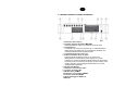
2. FUNZIONI E CONTROLLI PANNELLO FRONTALE fig.1 1. Interruttore d’accensione 2. Controllo generale del volume (MASTER) Questa manopola è usata per controllare il volume di uscita. 3. Controlli di tono I controlli di tono svolgono un intervento di +/- 10 dB nello spettro delle frequenze dei bassi ed acuti, permettendo di effettuare una corretta equalizzazione del segnale riprodotto. 4. Controlli di livello ingressi da 1 a 5 5. Indicatore di livello a led - Vu meter Indica il livello del segnale di uscita.
3. CONTROLLI PANNELLO POSTERIORE fig.2 1. Presa d’ingresso per alimentazione di rete (con fusibile) 2. Fusibile di protezione Protegge il dispositivo da eventuali sbalzi di tensione della rete di alimentazione e può essere sostituito. 3. Selettore per alimentazione di rete 230/117Vca 50/60Hz 4. Ingressi INPUT1 ~ INPUT4: a. Connettore d’ingresso COMBO/XLR b. Ingresso a morsetto estraibile eurobloc c.
5. Ingresso INPUT5: Esso prevede il collegamento di due sorgenti AUX (radio, cd, ecc.
.Morsetti attivazione funzione priorità Quando i terminali PRIORITY e COM vengono cortocircuitati, gli ingressi INPUT2 INPUT3, INPUT4 e INPUT5 si attenuano automaticamente lasciando la priorità di segnale all’ingresso INPUT1. 11.Morsetti SIREN Fintanto che, i due morsetti restano cortocircuitati, in uscita viene generato un tono sirena con priorità su tutti gli altri segnali ed il suo volume è regolato dal controllo MASTER. 12.Ingresso TEL.
• CONNESSIONE D’INGRESSO LINE (CD, TUNE, ecc) In caso di lunghe tratte utilizzare il cavo schermato. Riferendosi alla (fig.2 rif.4), settare il livello d’ingresso a livello LINEA, PIN1 a OFF. Posizionare il PIN4 a OFF (Alimentazione Phantom non attiva). Per applicazioni tipo parlato si consiglia di settare il PIN3 su ON.
• CONNESSIONE INGRESSO AUX (CD, TUNE, ecc.) In caso di lunghe tratte utilizzare il cavo schermato. Riferendosi alla (fig.2 rif.5) Settare quale, tra i due ingressi AUX disponibili, abilitare, PIN1 su ON è abilitato l’ingresso AUX2 su OFF quello AUX1 In base al livello del segnale d’ingresso, regolare la sensibilità mediante il PIN4, su ON la sensibilità d’ingresso è impostata a -10dbV su OFF la sensibilità d’ingresso è impostata a 0dbu Posizionare il PIN4 a OFF (Alimentazione Phantom non attiva).
LINEA AD IMPEDENZA COSTANTE Per ottenere una linea a impedenza costante collegare i due terminali rispettivamente al morsetto COM e a quello contrassegnato con il valore d’impedenza di linea desiderato (4, 8, 16Ω) (fig.2 rif.13). • Al fine di garantire il massimo rendimento, l’impedenza totale degli altoparlanti collegati alla linea, deve essere uguale all’impedenza dell’uscita dell’amplificatore.
b. Premendo il pulsante UP o DOWN per circa 2 secondi inizia la ricerca automatica delle stazioni radio che si ferma sulla prima stazione con un livello di segnale sufficiente. • RICERCA MANUALE. Se il segnale è scarso, l’utilizzo della ricerca automatica non risulta possibile, è quindi necessario ricorrere alla ricerca manuale. a. premere il pulsante AM/FM per selezionare la banda desiderata (AM o FM). b.
Funzioni: • OPEN/CLOSE. Premere questo pulsante per aprire/chiudere il cassetto porta CD. • PLAY/PAUSE. Avvia/sospende la riproduzione del brano. • LEVEL. Permette di controllare il volume del CD • STOP. Interrompe la riproduzione del CD. • B.SKIP/REV. Premendolo una sola volta la riproduzione si porta all’inizio del brano riprodotto. Premendolo due volte di seguito passa al brano precedente. Mantenendolo premuto si scorrono i brani indietro velocemente. • F.SKIP/FF.
7. RISOLUZIONE DI PROBLEMI Se il problema è… Il led non si accende con l’interruttore di accensione su ON. La ventola non gira. Il suono non si sente. • • • • • • L’uscita risulta intermittente, con ronzii e disturbi. L’uscita non è presente su uno o più canali. • • • Il display del CD non si accende. • Nessun segnale in uscita dal CD • Il segnale in uscita dalla radio è distorto, presenta molte interferenze o ha un livello di volume basso.
8. Caratteristiche Tecniche ACDT180 MODEL Output Power RMS Inputs 4 x MIC.
9.
1. IMPORTANT SAFETY INSTRUCTIONS CAUTION: To reduce the risk of electric shock do not remove cover (or back panel). No user serviceable parts inside. Refer servicing to qualified personnel only. WARNING: To reduce the risk of fire or electric shock, do not expose this apparatus to rain or moisture. This symbol is intended to alert the user of the presence of uninsulated dangerous voltage within the product enclosure that may be of sufficient magnitude to constitute a risk of electric shock to persons.
Sentences preceded by symbol contain important safety instruction. Please read it carefully. DETAILED SAFETY INSTRUCTIONS. Water and moisture: This apparatus should not be used near water (i.e. bathtub, kitchen sink, swimming pools, etc.) Ventilation: This apparatus should be placed in a position that doesn’t interfere with correct ventilation.
Objects or liquid entry inside the unit: Be careful that no objects fall or liquid is spilled inside the unit through ventilation openings. Safe power line use: • Keep firmly the plug and the wall outlet while disconnecting the unit from AC power. • If the unit will not be used for a long period of time, please unplug the power cord from AC power outlet. • To avoid unit power cord damages, please don’t strain the AC power cable and don’t bundle it.
• To obtain good speakers wire contacts, please tighten the screw terminals firmly. • For safety reason, don’t defeat the grounding connection. Grounding is useful for user safety. Use only connectors and accessories suggested by the manufacturer. . This unit should be placed in a rack (see INSTALLATION) and kept far from: Wet places Direct exposure to heat sources (like sun light) Non properly ventilated places Disconnect the power cord during storms or when the unit is not used.
Thank you for choosing one of Proel products, and for your confidence towards our brand, synonymous of professionalism, accuracy, high quality and reliability. All our products are CE approved and designed for continuous use in professional installation systems. 1. DESCRIPTION PA ACDT180 part has been designed for music programs diffusion and microphone announcement for all PA systems applications.
2. FUNCTIONS AND FRONT PANEL CONTROLS fig.1 1. Main switch power 2. Master volume control Such key allows the output volume control. 3. Tones control Tone control are possible for frequency interval between o +/- 10 dB for low and acute frequency band and ensure the correct reproduced signal equalizing . 4. Inputs level control From 1 up to 5 5. Led Level indicator - Vu meter It indicates the output signal level .
3. REAR PANEL CONTROL fig. 2 1. Main Power supply plug ( with fuse) 2. Protection Fuse It protects the unit against eventual power supply voltage variation. It can be replaced . 3. Main power supply voltage selector 230/117Vca 50/60Hz 4. Inputs INPUT1 ~ INPUT4: a. COMBO/XLR Input connector b. Euro block terminal – can be removed c. Dip-switch: PIN1 position ON=Input for a signal- Micro level position OFF=input for a signal-.
5. INPUT5: Input set for 2 AUX sources connections ( FM/AM Tuner, CD player etc..) through RCA input or Eurobloc removibile terminal Dip-switch: PIN1 PIN2 PIN3 PIN4 pos. ON = input AUX2 active pos. OFF =input AUX1 active pos. ON = no attenuation for both AUX inputs pos OFF = AUX input selected is 10 dB attenuated pos ON = high pass filter active in input pos OFF = no pass filter active in input pos ON = input sensibility set at -10dbV Pos OFF = input sensibility set at a 0dbu 6.
10.Priority functions activation terminal When PRIORITY and COM terminal are short circuited, INPUT2 INPUT3, INPUT4 e INPUT5 are automatically attenuated for the signal present in INPUT1 Priority status. 11. SIREN TERMINAL A tone chime with priority on all signals is generated when the two terminals are short circuited. Siren volume level can be set from MASTER control 12.TEL.PAGING Input Set to receive a high level telephone central audio signal (600Ω) ( balanced or unbalance) with priority on all signals.
• LINE INPUT CONNECTIONS(CD, AM/FM TUNER, etc..) I use shielded cable for long distance) Revert to (fig.2 ref.4), set input level to LINE level, PIN1 on position OFF ( Phantom power supply disabled ). Advice: for use for speech purposes set PIN3 on position ON.
• AUX INPUT CONNECTIONS (CD player , AM/FM TUNER etc..) I use shielded cable for long distance). Revert to (fig.2 ref.5) Set amongst the two AUX inputs available the one to be activated, PIN1 on position ON, AUX2 is activated –PIN1 on position OFF AUX1 is activated. Set the sensibility accordingly to input signal level through PIN4. PIN4 on position ON, input sensibility is set at -10dbV- PIN4 on position OFF input sensibility is set at 0dbu Setting PIN4 on position OFF Phantom power is disabled .
LINE AT CONSTANT IMPEDANCE In order to have a line at constant impedance, connet respectively the two terminal to COM and the one with the impedance line value selected (4, 8, 16Ω) (fig.2 ref.13). • To grant maximum performance, the total loudspeakers impedance must be equal the output amplifier impedance. • Total loudspeakers power must be lower than the amplifier output power . • Advice: the connections length should be reduced as far as possible .
d. Press UP or Down for about 2 seconds to start the automatic radio station research. Such research will be stopped as soon as the first radio station with a sufficient signal level is available • MANUAL RESEARCH. If the signal is very low, the automatic research is impossible and it is necessary to apply to the manual station research. c. Press key AM/FM to select the band (AM or FM). d.
Functions: • OPEN/CLOSE. Press this key to open and to close CD housing • PLAY/PAUSE. To start or to withhold the CD reproduction . • LEVEL. CD volume control • STOP. To interrupt the CD reproduction. • B.SKIP/REV. Pressing one time the current song reproduced restarts from the beginning . Pressing 2 times previous song is reproduced . Keeping this key pressed, the CD reproduction reverses . • F.SKIP/FF. Pressing one time the CD reproduction skips to the next song.
7. TROUBLES AND SOLUTIONS If the problem is… LED does not light when POWER switch is ON. No Ventilator action. No sound. Intermittance output signal with noise i. The output is not present on one or more channels . CD Display is not ON. NO CD output signal The radio signal output is distorted, with interferences and low volume level The radio output signal with intermittances and noise . The led level indicator is ON ma there is no signal in output. • • • • • • • • • • • • • • • • • • (ER..
8. Technical Characteristics ACDT180 MODEL Output Power RMS Inputs 4 x MIC.
9.
PROEL S.p.A. (World Headquarters - Factory) Via alla Ruenia 37/43 64027 Sant’Omero (Te) – Italy Tel: +39 0861 81241 Fax: +39 0861 887862 E-mail: info@proelgroup.com installation.proelgroup.