5SER -ANUAL SOUND PROELGROUP COM
AXIOM SERIES USER MANUAL Version 2.
c 2006-2008 Proel SpA Copyright Text and images by Daniele Ponteggia, Supervised by Remo Orsoni, Mario Di Cola, Rinaldo Grifoni cooperated for text and images in chapter 5, Cover art by Cinzia Calcagnoli. Version 2.0 - February 27, 2008 All contents of this manual are for the purpose of information and reference only; specifications and aspects of each product are subject to change at any time. Proel SpA is not responsible for any possible error in the contents of this manual.
Contents 1 Introduction 1.1 The sound out front! . . . . . . . . . . . . . . . . . . 1.1.1 Vertical Array Systems . . . . . . . . . . . . . 1.1.2 AXIOM Vertical Array Systems . . . . . . . . 1.1.3 Typical applications of AXIOM Vertical Arrays 1.2 Technological Solutions . . . . . . . . . . . . . . . . 1.2.1 Components . . . . . . . . . . . . . . . . . . 1.2.2 Technological Solutions . . . . . . . . . . . . . . . . . . . . . . . . . . . . . . . . . . . . . . . . . . . . . . . . . . . . . . . . . . . .
CONTENTS 5.3 5.4 5.5 5.6 5.7 5.8 CONTENTS 5.2.2 Stacking arrays of AX3210P and AX1118SP systems combined on flying bar KPTAX3210 . . . . . . . . . . . . . . . . . . . . . . . . . . . . . . . . . . . . . . . . . Suspending AX2265P and AX1115SP Systems . . . . . . . . . . . . . . . . . . . . . . . . 5.3.1 The suspension of AX2265P systems with KPTAX2265 flying bar . . . . . . . . . . 5.3.2 Flying an array of AX2265P and AX1115SP using flying bar KPTAX2265 . . . . . Stacking AX2265P and AX1115SP systems . .
1. Introduction 1.1 The sound out front! The AXIOM project was born when a careful analysis of the professional market revealed that one of its most urgent requests was for highly versatile and scalable products. Following the advances made with the development of the EDGE modular array project, Proel’s Research and Development Group has created several vertical array solutions that will satisfy the most demanding clientele in the widest range of applications.
1.1. THE SOUND OUT FRONT! 1. Introduction (a) (b) (c) Figure 1.1: Different designing approaches: (a) classic, (b) two-dimension array-ability, (c) vertical axle only arrayability. dimensions. Furthermore, while directivity can be shaped with a certain degree of freedom on a vertical line, on a horizontal line the directivity features of each element can be limiting4 .
1. Introduction 1.1. THE SOUND OUT FRONT! (a) (b) Figure 1.2: Vertical Array coverage, 16 modules @ 2kHz: (a) perfectly straight array, (b) progressive curvilinear array. extend the frequency range at which the interference between the sources can be controlled, even when their frequencies reach the highest levels.
1.1. THE SOUND OUT FRONT! 1. Introduction (a) (b) (c) (d) Figure 1.3: Vertical coverage stability comparison: (a) plan radiation sound system on straight array, (b) plan radiation sound system on curvilinear array, (c) curvilinear radiation sound system on straight array, (d) curvilinear radiation sound system on curvilinear array. Figure 1.4: AX3210P array with overhead AX1118SP subs, a typical employment of vocal sound reinforcement in an indoor arena.
1.1. THE SOUND OUT FRONT! # " $ " % & ' '& # () *+ , ! '& & " ! " &# "" ' " "" . &$/ ( ! '& # - - 1. Introduction , ! .
1.2. TECHNOLOGICAL SOLUTIONS 1. Introduction as, at equivalent power capability, their mounting complexity is remarkably reduced. 1.2 Technological Solutions The choice of AXIOM Systems project specifications was made considering the actual needs of our customers, the final users. Analysing such needs and combining the results with our professional experience in this field we laid the basis for our project of building functional versatile vertical array systems. We overlooked no detail.
1. Introduction 1.2. TECHNOLOGICAL SOLUTIONS Figure 1.7: AX2265P driver on wave guide 1.2.2 Technological Solutions When designing the AXIOM Series we went for top functionality, ignoring not even the slightest detail. The result is a mechanical system that is extremely easy to use and safe with an audio performance that is guaranteed in any situation. Integrated Suspension System The AXIOM Series Suspension System is fully integrated, with no need for external components, except the fly bar.
1.2. TECHNOLOGICAL SOLUTIONS 1. Introduction Figure 1.8: Amp-Ready back mechanics LAC Simulation Software In order to support the AXIOM Series Systems during the design phase and for daily use we developed a simulation software based on high resolution measurements of every element in the series and on advanced mathematical models.
2. Specifications All technical data reported here are the results of a series of tests run at Proel Labs in an anechoic chamber and in free field using state-of-the-art measurement methods. The measurements that resulted from such tests are the basis for the dedicated LAC simulation software and for the EASE commercial simulation software models. All updated models are available free of charge on our web site: sound.proelgroup.com.
AX3210P 2. Specifications AX3210P • VeCAM Module for high power curvilinear vertical arrays • Acoustic Coverage Improvement Device (A.C.I.D. Technology) • Integrated suspension and transportation systems • Amp Ready format Description Data Sheet Model AX3210P is a 3-way, full-range biamplifiable module for vertical arrays designed for live concerts or for permanent installations.
2. Specifications AX3210P Connectors mechanism for curvilinear vertical arrays, allowing the adjustment of the angle between each of the elements. The enclosures must be made of 15 mm birch plywood. The trapezoidal angle of the cabinets must be 12◦ . Dimensions should be: 32.1 cm high, 79.6 cm wide (front) and 66.5 cm deep. The system should be a PROEL AX3210P. 2 x Neutrik Speakon NL4MP, linked in parallel.
AX3210P 2. Specifications Polar diagrams (horizontal): 0° 30° 0° −30° 30° −12 30° −12 60° −60° −60° 60° −60° −36 90° 200Hz 250Hz 315Hz 400Hz −90° −36 90° −120° 120° −90° −150° 500Hz 630Hz 800Hz 1kHz 90° −120° 120° 150° −180° −90° −150° 150° −150° −180° 0° 0° −30° 30° −12 −30° −12 60° −60° 60° −60° −36 −36 90° −90° 3.15kHz 4kHz 5kHz 6.3kHz 90° −120° 120° 150° 1.25kHz 1.6kHz 2kHz 2.
2. Specifications AX1118SP AX1118SP • 18” neodymium woofer with ISV, DDR and DSS • Exponential vents • Integrated suspension and transportation systems • Amp Ready Format Description The AX1118SP is a direct radiation bass-reflex suspended subwoofer. AX1118SP complements AX3210P whenever extended bass frequency reproduction is required in the creation of a suspended array (model EDGE121SP from the EDGE Professional Series can also be used as ground stack subwoofer). The 18” woofer features a 5.
AX1118SP 2. Specifications Connectors 2 x Neutrik Speakon NL4MP linked in parallel.
2. Specifications AX1118SP Graphical data Frequency response1 : 10 0 SPL [dB] −10 −20 −30 −40 20 100 1k 10k 20k Frequency [Hz] Impedance: 100 90 80 Impedance [ohm] 70 60 50 40 30 20 10 0 10 100 1k Frequency [Hz] 1 Measured with 2.83 V @ 1m. with ground plane procedure in free field.
EDGE121SP 2. Specifications EDGE121SP • Direct Radiation Low-Frequency Enclosure • 21” Woofer with 4” ISV voice coil, DSS, DDR • Easy to transport Description 21” direct radiation subwoofer EDGE121SP can complete the bass response operating from 30 to 80 Hz, with an impressive excursion control and great power handling. It can operate at 800 W continuous (AES) and can handle peaks of 6 dB higher (3200 W) without problems or damage.
2. Specifications EDGE121SP Dimensions Graphical data Frequency response2 : Impedance: 100 Impedance [ohm] 80 60 40 20 0 12.5 2 Measured 31.5 63 125 250 500 Frequency [Hz] 1k with 2.83 V @ 1m. with ground plane procedure in free field.
AX2265P 2. Specifications AX2265P • VeCAM Module for high power curvilinear vertical arrays • Acoustic Coverage Improvement Device (A.C.I.D. Technology) • Integrated suspension system • Amp Ready format Description Data Sheet Model AX2265P is a compact module for underdimensioned Vertical Arrays that will surprise you with its quality and high pressure. AX2265P is a 2-way bi-amplifiable system designed for live concerts and permanent installations. It features two mid-low 6.
2. Specifications AX2265P Connectors of 15 mm birch plywood. The trapezoidal angle of the cabinets must be 12◦ . Dimensions should be: 32.1 cm high, 79.6 cm wide (front) and 66.5 cm deep. The system should be a PROEL AX3210P. 2 x Neutrik Speakon NL4MP, linked in parallel.
AX2265P 2. Specifications Polar diagrams (horizontal): 0° 30° 0° −30° 30° −12 30° −12 60° −60° −60° 60° −60° −36 90° −90° 120° 200 Hz 250 Hz 315 Hz 400 Hz −36 90° −120° −90° 120° −150° 500 Hz 630 Hz 800 Hz 1 kHz 90° −120° 150° −180° −90° 120° −150° −150° −180° 0° 0° −30° 30° −12 −30° −12 60° −60° 60° −60° −36 −36 90° −90° 120° 3.15kHz 4 kHz 5 kHz 6.
2. Specifications AX1115SP AX1115SP • 15” neodymium woofer with ISV, DDR and DSS • Exponential vents • Integrated suspension system • Amp Ready Format Description Model AX1115SP is a compact direct radiation bass-reflex subwoofer. AX1115SP can be suspended and complements AX2265P units both for suspended and stacked arrays, yielding coherent bass frequency reproduction, thus creating a 3-way system with a remarkable performance-dimension ratio.
AX1115SP 2. Specifications Connectors 2 x Neutrik Speakon NL4MP linked in parallel.
2. Specifications DSO26 DSO26 Descrizione Digital System Optimizer DSO26 is a digital processor with high audio quality thanks to the double precision signal elaboration offering a dynamic range greater than 110dB. DSO26 provides 2 inputs and 6 outputs3 and it is designed to operate in the following modes: 2x3-way, 4+2way, 5+1-way – with a mono sum output available – or 6-way.
DSO26 2. Specifications Data Sheet Inputs Impedance CMRR Outputs Source Imp Min. Load Max. Level Frequency Resp. Dynamic Range Distorsion Max Delay Min Step Size Gain Inputs Gain Outputs Parametric EQ Gain Freq.
2. Specifications LAC LAC Description The software is designed to be a quick and easy instrument for the best configuration of the system whether it is used by the most expert sound designer – who can use the array shading and singularly set the delay for each element – or by a beginner – who could profit from the auto-configure mode which will automatically optimize the curvature of the array.
3. Accessories The AXIOM Series features a complete line of accessories for the system’s installation and care. 3.1 Accessories for flown or stacked installation The fundamental element for flown or stacked installation of AX3210P and AX1118SP systems is fly bar KPTAX3210S, which optional feet, 95AXMPDN, allow installation in a stacked configuration. A compact version of fly bar KPTAX3210S is also available. You will find more information on its features and on load limits in chapter 5. (a) (b) Figure 3.
3.2. ACCESSORIES FOR TRANSPORTATION AND CARE OF THE SYSTEMS 3.2 3. Accessories Accessories for transportation and care of the systems Available caster-boards for transportation are: AXSKATE for AX3210P and AXSKATES18 for AX1118SP. Available for model AX3210P, there is also cover 93COVAX310 and soft cover COVERAX3210. There are also transport cases: CP038D04 for four AX2265P, CP038C04 for two AX1115SP. 3.
3. Accessories 3.4. SUSPENSION TOWERS AND ENGINES (a) (b) Figure 3.4: Transportation accessories: 3.4a AX3210P on AXSKATE caster-board and 93COVAX310 cover, 3.4b AX1118SP on AXSKATES18 caster-board. (a) (b) (c) Figure 3.5: Transportation accessories: 3.5a CP038D04 case for 4 x AX2265P, 3.5b AX2265P on case (open), 3.5c CP038A04 case for 2 x AX3210P.
4. Sound design with AXIOM Vertical array systems offer a series of advantages when compared to traditional systems, and we discussed them extensively in the introduction to this manual. Nonetheless, because of the high quantity of sources employed, vertical array systems present a natural complexity which needs to be dealt with correctly. A careful acoustic and mechanical design when configuring the installation will help face such complexity painlessly.
4.2. DESIGN INSTRUMENTS 4. Sound design with AXIOM vertical array systems we use the centralized approach to sound reinforcement, and the modality which allows the creation of a single, large source has already been treated in detail when we discussed array-ability.
4. Sound design with AXIOM 4.2. DESIGN INSTRUMENTS Figure 4.1: LAC Vertical View window increasing angle sequence. Whatever the changes made, the sequence should follow an increasing pattern. This allows the greatest uniformity of vertical dispersion, and the distance SPL graph will fully confirm it, at any frequency. The Advanced button leads to another window where you can set some more parameters (power level and delay of each single element) which by default have been set to zero.
4.2. DESIGN INSTRUMENTS 4. Sound design with AXIOM Figure 4.2: LAC Mechanical View window is like calculating respectively for 3, 5 or 7 points within the chosen band segment. Once all the simulation parameters have been set, the calculation motor can be started by pressing the Start button in the Simulate module. The feed bar will show the calculation phases and at the end the direct range map for the configuration chosen will come up.
4. Sound design with AXIOM 4.3. FLOWN OR STACKED ARRAYS configuration, the load on each motor is automatically recalculated. The LAC software does not take into account the power cable weight, and the position of the array, once mounted, could be different from the simulated one7 . From the Mechanical view window, if you click on the left box, you can switch immediately to the Vertical View window, and the different pointer symbol indicates you’ve switched area.
4.4. THE CURVATURE OF THE ARRAY 4.4 4. Sound design with AXIOM The curvature of the array Directivity on the vertical axis of an array of sources depends on the shape of the array. We know that perfectly straight arrays create a very narrow central lobe, which is a problem in most typical sound reinforcement applications. The solution which proved to be the most effective for typical sound reinforcement applications is the employment of arrays with a progressive curvature9 .
4. Sound design with AXIOM 4.5. SYSTEM PROCESSING Figure 4.5: EDGE121SP+AX3210P preset structure 4.5.1 AX3210P System Processing AX3210P are three-way systems with a passive filter that feeds the two coaxial membranes of the high frequency driver. AX3210P systems are processed as two-way: MID-L and HIGH.
4.6. THE LOW RANGE 4. Sound design with AXIOM Figure 4.6: Typical frequency response for vertical arrays (a) (b) Figure 4.7: Simplified pattern of the combination mechanism for the elements of the array: (a) low frequencies (b) high frequencies. 4.
4. Sound design with AXIOM 4.7. NOTES ON THE POWER OF THE AMPLIFICATION Figure 4.8: Simulation of emission produced by 12 EDGE121SP subs set in 2 groups of 6 and positioned L+R. Figure 4.9: Simulation of emission produced by 12 EDGE121SP subs set in 4 groups of 3 and distributed across the stage front. practical problems of space.
4.7. NOTES ON THE POWER OF THE AMPLIFICATION 4. Sound design with AXIOM value and peak value ratio) of 6 dB. For common applications which require both a high power and a high reliability level, it is advisable to use power amplifiers with an output rating equivalent to the AES power rating of the enclosures. This ensures that the enclosures will operate within their thermal limit specification.
5. Guide to System Setup This chapter of the manual is devoted to the mounting procedures necessary to fly or stack the AXIOM Series Curvilinear Vertical Array Systems. The AXIOM Systems are built to allow the suspension of arrays with variable shape and dimensions thanks to a suspension mechanism designed to be functional, flexible and safe. The loudspeakers are linked together in a column using a series of couplers integrated in the frame of each enclosure.
5.1. SUSPENDING AX3210P AND AX1118SP SYSTEMS 5. Guide to System Setup Figure 5.1: AX3210P - integral suspension system The LAC software simulates the acoustic operation of the array, and defines the position of its barycentre and consequently the coupling points for the configuration chosen.
5. Guide to System Setup 5.1. SUSPENDING AX3210P AND AX1118SP SYSTEMS Mounting operation sequence According to the correct mounting procedure, the creation of the array has to be started on the ground, with AX3210P systems on their caster boards, and then lifted. All front coupling operations and most of the wiring can be done on the ground. This allows the quick and easy assembly of the array, without having to worry about taking away the caster boards in this phase.
5.1. SUSPENDING AX3210P AND AX1118SP SYSTEMS 5. Guide to System Setup Figure 5.3: Array prepared on a uneven ground In the A configuration, the attachment of the flying bar is rather easy: move KPTAX3210 flying bar vertically close to the top enclosure on the array, then use the cams on the flying bar to couple it to the front of the enclosure. The posterior bars need to be fastened to the coupling housings in the rear of the flying bar, in the seats created by the L-folded plates welded to the crossbars.
5. Guide to System Setup 5.1. SUSPENDING AX3210P AND AX1118SP SYSTEMS Figure 5.4: Correct coupling point between the hole in the posterior bars and the flying bar. 6. The flying bar is coupled with the enclosure and fixed with pins • Coupling the flying bar with the lifting device The flying bar and the lifting device are coupled through the insertion of 22 mm shackles in the numbered holes on the bar itself.
5.1. SUSPENDING AX3210P AND AX1118SP SYSTEMS 5. Guide to System Setup Figure 5.5: Array coupled in the front and ready (on the left) and power wiring (on the right). During the lifting phase check continuously to make sure that the space between each loudspeaker and the next is free and that the lifting is smooth. If jams were to occur or if cables were to enter the space between the enclosures, do not try to free them during compression or lifting.
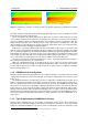
5. Guide to System Setup 5.1. SUSPENDING AX3210P AND AX1118SP SYSTEMS Figure 5.6: Pins are inserted through the U-shaped profile and the slotted bar 8. The angles are set by inserting the pins Figure 5.7 shows some mounting examples with the angle set at 0◦ , 10◦ and 10.5◦ . Next, you see a table for all possible configurations.
5. Guide to System Setup 5.1. SUSPENDING AX3210P AND AX1118SP SYSTEMS Figure 5.
5. Guide to System Setup 5.1. SUSPENDING AX3210P AND AX1118SP SYSTEMS 9. The array is lifted further 10. The array is completely set At the end of these operations the last element of the array still lies on the ground and the array is ready to be lifted.
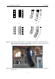
5.1. SUSPENDING AX3210P AND AX1118SP SYSTEMS 5. Guide to System Setup Figure 5.8: Caster boards are disengaged and stacked. • The array is lifted off the ground In this phase the array has to be eased in its natural movement by holding the handles on the last enclosure of the array to avoid a sharp forward shifting toward the natural vertical centre provided by the lifting point. We advise operating on the vertical lifting point as much as possible in order to keep the array from shifting forward.
5. Guide to System Setup 5.1. SUSPENDING AX3210P AND AX1118SP SYSTEMS As the array is being lifted, you can take away the caster boards. To disengage the boards press and turn the catch pins. This operation is rather simple and it does not require more than one operator. 12.
5.1. SUSPENDING AX3210P AND AX1118SP SYSTEMS 5. Guide to System Setup ) ! % $ & ' ( ) * +) - . ! " % $ " #$ #$ %#$ $ & ' ( & % , ) ! % $ & ' ( % $ & ) * +) - .
5. Guide to System Setup 5.1.2 5.1. SUSPENDING AX3210P AND AX1118SP SYSTEMS Flying an array of AX3210P and AX1118SP using flying bar KPTAX3210 Flying bar KPTAX3210 allows the suspension of systems composed by AX3210P and AX1118SP6 . Array configuration choice We discussed the advisability of systems composed with suspended subwoofers in the preceding chapter. The LAC software will simulate the acoustic behaviour of the system, define its barycentre and determine the mechanical configuration of the system.
5.1. SUSPENDING AX3210P AND AX1118SP SYSTEMS ) * %+ ! " # ,! $ ,! ,! ! " # ! ! $ " " % & '% # ( 5.
5. Guide to System Setup 5.2. STACKING AX3210P AND AX1118SP SYSTEMS Figure 5.11: KPTAX3210S – Coupling configuration Technical Office. 5.2 Stacking AX3210P and AX1118SP systems Stacked AXIOM Systems arrays can be created either using an AX1118P SUB directly on the ground as a base or employing flying bar KPTAX3210 adding its feet (95AXMPDN).
5.2. STACKING AX3210P AND AX1118SP SYSTEMS 5.
5. Guide to System Setup 5.2. STACKING AX3210P AND AX1118SP SYSTEMS Figure 5.13: KPTAX3210 – positioned on the ground Sequence of mounting operations • Positioning flying bar KPTAX3210 on the ground Mount feet 95AXMPDN on top of the flying bar (on the same side where the suspension shackle is), then put the bar down on the ground in the position where you will stack the array and adjust the feet so to lie the bar perfectly horizontal.
5.2. STACKING AX3210P AND AX1118SP SYSTEMS 5. Guide to System Setup Figure 5.14: KPTAX3210 – adjusting the angle of the first enclosure 2. Coupling the bar with the first enclosure of the stacked array • Positioning the first portion of the array on the ground Once the first enclosure has been coupled to the flying bar, with a rotation you can lie this portion of the array back on the ground in the position you had marked.
5. Guide to System Setup 5.2. STACKING AX3210P AND AX1118SP SYSTEMS Figure 5.15: position of lateral pins used as anti-shifting pins ! Figure 5.16: Adjusting the relative angle between AX3210P and AX1118SP systems when stacked 3.
5.2. STACKING AX3210P AND AX1118SP SYSTEMS 5. Guide to System Setup 4. Front coupling 5. Setting the angle with the back slotted bar Verify that the angle has been set correctly on both slotted bars of the enclosure. You can now proceed iteratively to complete the assembly of the whole stacked array. • Removing the caster boards Once you have completed the array you can remove the caster boards and put them away.
5. Guide to System Setup 5.2. STACKING AX3210P AND AX1118SP SYSTEMS Sequence of mounting operations • Positioning flying bar KPTAX3210 on the ground Mount feet 95AXMPDN on top of the flying bar (on the same side where the suspension shackle is), then put the bar down on the ground in the position where you will stack the array and adjust the feet so to lie the bar perfectly horizontal. Obviously, the ground needs to be absolutely stable and compacted.
5.3. SUSPENDING AX2265P AND AX1115SP SYSTEMS 5. Guide to System Setup Load limits Flying bar KPTAX3210 can stack up to eight systems. The following chart shows all the possible combinations: AX3210P 8 6 4 2 0 5.3 AX1118SP 0 1 2 3 4 Suspending AX2265P and AX1115SP Systems AXIOM models AX2265P and AX1115SP feature a suspension system integrated into their frames features two coupling cams in the front of the speaker and two slotted bars in the back.
5. Guide to System Setup 5.3. SUSPENDING AX2265P AND AX1115SP SYSTEMS Choosing the array configuration Because of the great variety of possible configurations, AXIOM systems are provided with a software (LAC) which allows the simulation of the array configuration, therefore calculating the centre of mass and the anchoring points. The LAC software simulates the acoustic operation of the array, and defines the position of its barycentre and consequently the coupling points for the configuration chosen.
5.3. SUSPENDING AX2265P AND AX1115SP SYSTEMS 5. Guide to System Setup • Enclosure front coupling on the ground The operation of coupling the front part of the enclosures is quite simple: get the speakers on their case boards close together and release the pins holding the cams, then slide the cams into their housing on the next speaker and fasten them into their new position with the pins. Now you can proceed iteratively with the following steps necessary to mount the array. 1.
5. Guide to System Setup 5.3. SUSPENDING AX2265P AND AX1115SP SYSTEMS Figure 5.19: AX2265 array ready for wiring Figure 5.
5.3. SUSPENDING AX2265P AND AX1115SP SYSTEMS 5. Guide to System Setup 4. The flying bar is coupled with the enclosure and fixed with pins 5. Set the angle between the flying bar and the first enclosure • Coupling the flying bar with the lifting device The flying bar and the lifting device are coupled through the insertion of 16 mm shackles in the numbered holes on the bar itself. The indication of the correct hole to use will be provided by the LAC simulation software.
5. Guide to System Setup 5.3. SUSPENDING AX2265P AND AX1115SP SYSTEMS During the lifting phase check continuously to make sure that the space between each loudspeaker and the next is free and that the lifting is smooth. If jams were to occur or if cables were to enter the space between the enclosures, do not try to free them during compression or lifting. Never try to operate in the space between the loudspeakers while they are being hoisted.
5.3. SUSPENDING AX2265P AND AX1115SP SYSTEMS 5. Guide to System Setup Figure 5.21: AX2265P array is lifted off the ground 8. The array is lifted further 9. The array is completely set At the end of these operations the last element of the array still lies on the ground and the array is ready to be lifted.
5. Guide to System Setup 5.3. SUSPENDING AX2265P AND AX1115SP SYSTEMS 10. The array is completely off the ground • Arranging the position of the array At this point the array can be lifted to the desired height and fastened with ropes to avoid its rotation or oscillation due to the wind, especially when you are using only one flying point. Once the array has been positioned correctly, the flying device has to be checked to assure safety according to all current local and national regulations.
5.3. SUSPENDING AX2265P AND AX1115SP SYSTEMS 5. Guide to System Setup ) ! " % & ' ( ) * +) - . " # ( # $ %$ &$ ' ( % , ) ! " % & ' ( % & ) * +) - .
5. Guide to System Setup 5.4. STACKING AX2265P AND AX1115SP SYSTEMS Sequence of assembly operations The sequence of the assembly operations is exactly the same as described for arrays composed only of AX2265P. The only exception is the angle setting which is different when you have to couple AX2265P systems with AX1115SP. AX1115SP systems feature a frame like the one mounted on AX2265P systems, which has a slotted bar for coupling purposes.
5.4. STACKING AX2265P AND AX1115SP SYSTEMS ) * %+ $ ! " # , $ , , ! ! ! " # $ % & '% # ( 5.
5. Guide to System Setup 5.4.1 5.4. STACKING AX2265P AND AX1115SP SYSTEMS Stacking AX2265P systems on flying bar KPTAX2265 Choosing the array configuration The array configuration is limited by the fact that, when stacked, the systems can only maintain partial angles because only the hole on the slotted bar, and not the slot, can be used to couple them13 . Flying bar KPTAX2265 used as stacking base Flying bar KPTAX2265 with its rubber feet can be used to stand AXIOM System Stacked Arrays safely.
5.4. STACKING AX2265P AND AX1115SP SYSTEMS 5. Guide to System Setup Sequence of mounting operations • Positioning flying bar KPTAX2265 on the ground put the bar down on the ground in the position where you will stack the array and adjust the feet so to lie the bar perfectly horizontal. Obviously, the ground needs to be absolutely stable and compacted.
5. Guide to System Setup 5.5 5.5. NOTES ON SAFETY Notes on safety Although this manual contains a lot of useful information for the suspension of vertical array systems, it is not enough to cover the subject in all its complexity: it is therefore necessary to rely on qualified and expert operators when you need to mount a vertical array. The user/installer will have the responsibility of verifying all load limits and procedures constraints related to the suspension of the array.
5.7. WHAT YOU NEED TO DO 5. Guide to System Setup Therefore, it is the user’s responsibility to make sure that the suspension system features meet all criteria required by local laws and regulations. Nonetheless, it is the user’s responsibility to make sure that the system is mounted right, according to its load limits and to all indications reported here. The product must be installed only by qualified operators without exceeding the load limits and in the respect of all indications given by this guide.
6. Operating guide In this chapter we will describe the series of practical operations needed for the use of the AXIOM Systems. We will not discuss the mounting, to which we devoted chapter 5. This chapter could be used as a step-by-step guide that can lead you through mounting choices and execution, verification of correct mounting, equalization and setting and finally disassembly and storage of the system. You will also find information on care and preservation of the AXIOM systems . 6.
6.2. COMPONENTS TESTING 6.1.3 6. Operating guide Test Signal generator When verifying the operativeness of the system and its equalization, it is essential to have a signal generator that can at least generate pink noise. If measurement software is used, this function is usually included, but an inexpensive alternative is to have a CD with pre-recorded pink noise. 6.1.
6. Operating guide 6.3 6.3. SYSTEM DESIGN System Design Every time that the system is to be installed, it is necessary to simulate it with the LAC software application. In chapter 4, we have covered this subject in detail, and it is to be emphasized here that the design and simulation of the installation is part of the setup procedure and should never be omitted.
6.4. INSTALLATION OF THE SYSTEM 6.4.2 6. Operating guide Adjustment Once the system has been installed and its correct operation has been confirmed, proceed to the regulation of the SUB output. SUB delay The presets supplied by Proel with the AXIOM system foresee the mechanical alignment of the satellites with the subwoofer systems. Therefore the system is correctly aligned when one satellite is physically above one sub enclosure; the situation shown in figure 6.2.
6. Operating guide 6.4. INSTALLATION OF THE SYSTEM point P and the flown array. This can be done with a laser range finder or calculated trigonometrically using the measured distance from the Sub to point P, and the measured distance between the vertical axis of the flown array and point P and the known height of the flown array.
6.4. INSTALLATION OF THE SYSTEM 6. Operating guide Figure 6.6: Delay adjustment, SUB signal lags in phase. proceed with the physical measurement of the distances involved and utilize the values obtained from this to set the delay in the processor. This method will allow you to begin with a delay value which is very close to that which is exact, without introducing possible errors caused by uncertainty, misuse or malfunction of the external measurement instrumentation.
6. Operating guide 6.4. INSTALLATION OF THE SYSTEM Figure 6.7: Delay adjustment, SUB signal ahead in phase. Figure 6.8: Delay adjustment, SUB signal perfectly in phase.
6.5. DURING THE SHOW 6. Operating guide the subs or, given that the frequencies are high, with the automatic delay finder function of SmaartLive (or with an impulse peak alignment function of other measurement systems). Equalization At this point the system should be completely and correctly set up with regard to time alignment, and it is possible to proceed with any necessary equalization. Equalization requires a notable level of ability and experience on the part of the operator.
6. Operating guide 6.5. DURING THE SHOW of the sound reinforcement system: the system is not adapted to the sound pressure levels required by the situation. 6.5.2 Equalization adjustment The changes in atmospheric and environmental conditions between the set up of the system and the actual performance can be quite noticeable. In closed venues, the arrival of the audience drastically augments the acoustic absorption characteristics of the room, with consequential changes in the reverberation decay time.
7. Typical applications The AXIOM systems have been designed to be extremely modular. The following chapter, shows an example of some of the typical applications for live concert systems and fixed installations. These are just few of the many possible configurations of the AXIOM system. 7.
7.2. MEDIUM CONCERT SYSTEM 2 7.2 7. Typical applications Medium concert system 2 !"#$%!&'$!( ) * !+', - ./'' !01 !"#$ /1 (232#$ - ./'' !01 !"#$ /1 (232#$ - .
7. Typical applications 7.3 7.3. COMPACT CONCERT SYSTEM Compact concert system ( # )&*+ %"* ' , - !".
Appendix A Vertical Array theory Vertical arrays, commonly referred to as line arrays, have earned enormous popularity among professional users. The fundamental principals used as a basis of the design and operation of these electro acoustic systems unfortunately have not enjoyed the same proliferation as the systems themselves.
A.2. WAVE FRONTS AND SOURCE CURVATURE A. Vertical Array theory Figure A.1: Simulation of the radiation along the vertical axis of an array composed of 16 omnidirectional sources with a step of 32cm. while off axis these contributions tend to cancel out due to the differences in radiation path and, consequently, in phase. Furthermore, it can be verified that the control of directivity at low frequencies is dependent on the overall length of the array.
A. Vertical Array theory A.2. WAVE FRONTS AND SOURCE CURVATURE than a continuous flat source. If we compare the polar diagram of a continuous flat source to an array of curved sources, we see that the dispersion is very similar, with small differences only in the lateral lobes. Imposing the condition that the lateral lobes remain at a level of at least 10dB lower than the central lobe, we find that the curvature of the source is one-fourth the wavelength of the lowest frequency it must reproduce.
Appendix B Notes on system measurement The measurement of the response of audio systems can be carried out either with a real-time spectrum analyzer or with an instrument capable of revealing the complex response, including modulus and phase. If we model the system to be measured as a Linear Time-Invariant system1 , it is possible to analyze its operation by means of the character of its frequency response. B.
B.2. THE PERFECT SYSTEM B.2 B. Notes on system measurement The Perfect System For a system to be perfect or, rather, for it to be free of linear distortion, theoretically it must have a flat mode response (in the band of interest) and a linear phase response (if visualized on a linear frequency scale). Figure B.
B. Notes on system measurement B.4. ENVIRONMENTAL REFLECTIONS spectrum of the output as the response of the system. With this method, we are given no information about phase. In order to acquire data about phase response, it is necessary to use an instrument of measure more complex that utilizes test signals known to the instrument (the pink noise to which we referred previously is known only for its frequency content, but not for its temporal content).
B.5. SELECTION OF A MEASUREMENT MICROPHONE B. Notes on system measurement (a) (b) Figure B.4: Measurement microphones position: (a) on microphone boom stand, (b) in ground-plane. to the use intended for the results of the measurement. For time alignment of the Subs, it is necessary to position the microphone in the ground plane. B.
B. Notes on system measurement B.6. MONO OR STEREO MEASUREMENT? case, however, it is necessary to use the measurement system in a very critical manner. Real time analysis is based on a mono source, a pink noise generator, and therefore the Left and Right channels will reproduce the same signal. It is therefore possible to move about the listening area to measure the frequency response.
Appendix C Useful Formulae and Tables In this appendix we review some formulae and reference tables useful in the everyday use of the AXIOM vertical array system. C.1 Calculation of the speed of sound The velocity of the propagation of sound c in air depends fundamentally on the temperature according to the formula: m c = 331.4 + 0.6 · T s where T is temperature in ◦ C. C.
C.3. CONVERSION DELAY-DISTANCE AND DISTANCE-DELAY C.3 C. Useful Formulae and Tables Conversion Delay-Distance and Distance-Delay When the speed of sound is known, the relationship between time delay t in milliseconds and distance d in meters can be expressed be the following: t = 1000 · d= C.4 d [ms] c t ·c [m ] 1000 Notions of Trigonometry Sometimes it is not possible to use measurement tools such as laser range finders.
C. Useful Formulae and Tables C.5. AIR ATTENUATION Attenuation of sound in air (50m) 0 −5 Attenuation [dB] −10 −15 −20 20% 40% 60% 80% −25 −30 1k 10k 20k frequency [Hz] Figure C.1: Attenuation in function of relative humidity at a distance of 50m. This table presents some attenuation values, expressed in dB/km, for vaious levels of relative humidity and at a temperature of 20◦ C: freq. [Hz] 1 1.25 1.6 2 2.5 3.15 4 5 6.3 8 10 12.
352(/ ,QWHUQDWLRQDO /WG /RQGRQ 8. 352(/ %(1(/8; (OVW *OG 352(/ '(876&+/$1' *PE+ (PVGHWWHQ 1(7+(5/$1'6 '(876&+/$1' 352(/ $8675,$ *PE+ 352(/ )5$1&( 3DULV 1HXPDUNW )5$1&( $8675,$ 352(/ 86$ ,QF 352(/ 6 S $ (O 3DVR 7; :RUOG +HDGTXDUWHUV )DFWRU\ 352(/ .25($ &2 /7' 86$ ,7$/< .25($ 352(/86$ 352'8726 086,&$,6 /'$ *\XQJJL 'R 352(/ *5283 ($67 $6,$ /7' &DVDLV 7RPDU +21* .