
User manual


4. Sound design with AXIOM 4.2. DESIGN INSTRUMENTS
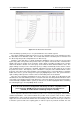
Figure 4.1: LAC Vertical View window
increasing angle sequence. Whatever the changes made, the sequence should follow an increasing
pattern. This allows the greatest uniformity of vertical dispersion, and the distance SPL graph will fully
confirm it, at any frequency.
The Advanced button leads to another window where you can set some more parameters (power
level and delay of each single element) which by default have been set to zero. A skilled operator should
be the one setting the delay between each element, but level shading is a procedure which employment
we advise in many installations, as it limits remarkably the differences in level between the areas closest
to the system and those further away from it. As it is possible to tell the software about such variations,
it will allow the simulation of their effects.
5
.
Once the structure of the location and of the whole array has been determined, a simulation can cal-
culate how the direct sound range emanated by the whole array is distributed. This acoustic simulation
is carried out one frequency at a time and the frequency has to be chosen among the ISO frequencies
available in the proper pull-down menu. The distribution of the direct range is represented by a colour
map. This map will disappear from the screen every time a parameter that can influence the simula-
tion’s result is inserted. In this case the distribution simulation has to be recalculated. Obviously, the
calculation is not completely punctual, but in a neighbourhood of the frequency you can select.
The pull-down menus in the Simulate module allow the choice of the simulation frequency and of
the average that needs to be applied. Parameter Map Res indicates the dimension of the area module
on which the colour map is calculated. If you were to partition the whole vertical view surface in a
certain number of squares, Map Res would indicate the dimension of the side of each square: it can
vary between 0.1 (10 cm) and 5 (5 m). Parameter Source Res indicates which resolution is employed to
partition the source (the whole array)
6
. If those parameters are modified for accuracy, calculation time
will be lengthened. Finally, parameter BW Accuracy allows the choice of how many points within the
frequency neighbourhood are to be used for the calculation. Thus, for any of the band widths admitted
for calculation (1/3, 1/6, 1/12, 1/24 of an octave) the accuracy values can be Low, Medium or High, which
5
The attenuation of the lower part of the array is a rather common practice, but it is not completely painless, as the length of
the array gets shorter and consequently the directivity control in the lower-mid range decreases.
6
For example, a figure of 0.02 indicates that the array has been vertically divided into 2 cm-high pieces. If we were only
interested in the simulation results referring to the low range, we could use Source Res figures as high as 0.1 (10 cm), thus
increasing the simulation speed remarkably.
33