
User manual


5.1. SUSPENDING AX3210P AND AX1118SP SYSTEMS 5. Guide to System Setup
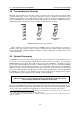
Figure 5.1: AX3210P - integral suspension system
The LAC software simulates the acoustic operation of the array, and defines the
position of its barycentre and consequently the coupling points for the configuration
chosen. The structural resistance of each component needs to be verified by the
operator who installs the system, unless the configuration chosen is one of those
advised by the manufacturer. For further details, see the section devoted to load
limits.
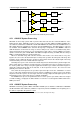
Flying bar KPTAX3210
Flying bar KPTAX3210 features two possible configurations for lifting the systems, one anterior (config-
uration A) and one posterior (configuration B), also referred to as reverse mode. The bar features four
coupling cams that can be set in the lateral bars by the insertion of 94AXMSP1 coupling pins.
Figure 5.2: KPTAX3210 – Coupling configurations
42