
User manual


5.1. SUSPENDING AX3210P AND AX1118SP SYSTEMS 5. Guide to System Setup
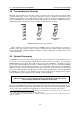
Figure 5.3: Array prepared on a uneven ground
In the A configuration, the attachment of the flying bar is rather easy: move KPTAX3210 flying bar
vertically close to the top enclosure on the array, then use the cams on the flying bar to couple it
to the front of the enclosure. The posterior bars need to be fastened to the coupling housings in
the rear of the flying bar, in the seats created by the L-folded plates welded to the crossbars. To
obtain a correct assembly, the relative angle between the flying bar and the first enclosure of the
array has to equal 0
◦
: to do so insert 94AXSMP1 pins through the second hole from the top in the
flying bar and through the hole of the bar.
Please note that, in the back of the array, the pin stays on the enclosure, whereas in the front the
pin is used on the enclosure immediately below.
5. Pins are disengaged and cams are extracted from KPTAX3210 flying bar
44