
User manual


5.1. SUSPENDING AX3210P AND AX1118SP SYSTEMS 5. Guide to System Setup
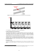
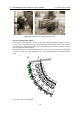
Figure 5.5: Array coupled in the front and ready (on the left) and power wiring (on the right).
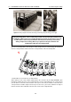
During the lifting phase check continuously to make sure that the space between each
loudspeaker and the next is free and that the lifting is smooth. If jams were to occur or
if cables were to enter the space between the enclosures, do not try to free them
during compression or lifting. Never try to operate in the space between the
loudspeakers while they are being hoisted.
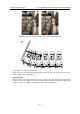
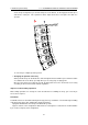
Once the first loudspeakers of the array are under compression you can disengage the slotted bar
from its U-shaped frame and insert it in the U-shaped frame of the next loudspeaker.
7. Slotted bars are inserted in the U-shaped frame
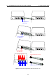
At this point you can set the relative angle between the enclosures by inserting 94AXSMP1 pins
through the numbered holes on the U-shaped frame or in the slotted bar itself. To couple the bar
you can either use the hole at its end or the slot. If you use the slot, the numbers next to the holes
correspond to the relative angle; instead, if you use the hole, you need to subtract 1.5 degrees
from the numeric value indicated next to the hole used on the U-shaped frame.
46