
User manual


5. Guide to System Setup 5.1. SUSPENDING AX3210P AND AX1118SP SYSTEMS
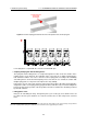
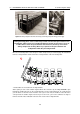
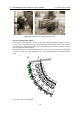
Figure 5.6: Pins are inserted through the U-shaped profile and the slotted bar
8. The angles are set by inserting the pins
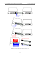
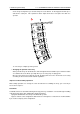
Figure 5.7 shows some mounting examples with the angle set at 0
◦
,10
◦
and 10.5
◦
. Next, you see
a table for all possible configurations.
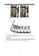
• Lifting proceeds
Once the angle of the first enclosures has been set, you can continue lifting the array, putting
another section under compression and proceeding iteratively, setting the angle of the subsequent
enclosure one by one using the corresponding hole in the U-shaped frame.
47