
User manual


5. Guide to System Setup 5.2. STACKING AX3210P AND AX1118SP SYSTEMS
Sequence of mounting operations
• Positioning flying bar KPTAX3210 on the ground
Mount feet 95AXMPDN on top of the flying bar (on the same side where the suspension shackle
is), then put the bar down on the ground in the position where you will stack the array and adjust
the feet so to lie the bar perfectly horizontal. Obviously, the ground needs to be absolutely stable
and compacted.
At this point mark the position of the bar on the ground and lift it up vertically.
• Coupling the first subwoofer enclosure with KPTAX3210
The first subwoofer enclosure of the array is coupled to the bar following the same procedure
described for the suspension of the array, that is the bar is coupled to the enclosure still mounted
on its caster board.
Couple the front cams of the flying bar to the front bars on the enclosure and fasten them with the
pin.
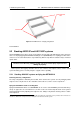
Couple the back slotted bar to the flying bar inserting the pin in the hole of the slotted bar and in
the coupling frame of bar KPTAX3210. The coupling frame features four holes corresponding to
four different angles between the first enclosure and the flying bar. The subwoofer AX1118SP has
to be at a 0
◦
angle, therefore you need to use the hole corresponding to 0
◦
(see figure 5.14).
• Positioning the first portion of the array on the ground
Once the first enclosure has been coupled to the flying bar, with a rotation you can lie this portion
of the array back on the ground in the position you had marked.
To avoid backward shifting of the array you have to use two 94AXMSPI pins and insert them in the
proper housings on the lateral crossbar of the flying bar.
• Coupling next subwoofers AX1118SP
You can stack another AX1118SP subwoofer on the array lifting it up and placing it upside down on
top of the array. Now you can couple its front cams to the frame of the enclosure underneath, then
the hole in the slotted bars on the back and the hole corresponding to 0
◦
in the U-shaped frame of
the enclosure underneath, and insert the pin to secure their position.
Make sure you have set the correct angle for both back slotted bars on the enclosure.
You can now proceed iteratively and stack all AX1118SP systems.
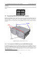
• Coupling next loudspeakers AX3210P
You can stack the next enclosure of an AX3210P loudspeaker on the array lifting it up and placing
it upside down on top of the array. Now you can couple its front cams to the frame of the enclosure
underneath and insert the pins to block them. Then lift the back part of the enclosure and set the
relative angle using the hole in the slotted bars on the back and the hole in the U-shaped frame of
the enclosure underneath, and insert the pin to block their position (figure 5.16 shows the possible
mounting angles).
Make sure you have set the correct angle for both back slotted bars on the enclosure.
You can now proceed iteratively until the completion of the array.
• Removing the caster boards
Once the array has been completely stacked you can remove the caster boards and put them
away.
Sequence of disassembly operations
Disassembly works the same way assembly does, simply inverting the order of the operations.
61