
User manual


5. Guide to System Setup 5.3. SUSPENDING AX2265P AND AX1115SP SYSTEMS
Choosing the array configuration
Because of the great variety of possible configurations, AXIOM systems are provided with a software
(LAC) which allows the simulation of the array configuration, therefore calculating the centre of mass
and the anchoring points.
The LAC software simulates the acoustic operation of the array, and defines the
position of its barycentre and consequently the coupling points for the configuration
chosen. The structural resistance of each component needs to be verified by the
operator who installs the system, unless the configuration chosen is one of those
advised by the manufacturer. For further details, see the section devoted to load
limits.
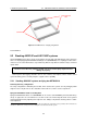
Flying bar KPTAX265
Flying bar KPTAX2265 features two possible configurations for lifting the systems, one anterior (config-
uration A) and one posterior (configuration B), also referred to as reverse mode.
Figure 5.18: KPTAX2265 – Coupling configurations
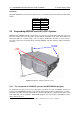
Mounting operation sequence
According to the correct mounting procedure, the creation of the array has to be started on the ground,
with AX2265P systems on their case boards (case code CP038D04 for 4 AX2265P systems), and then
lifted. All front coupling operations and most of the wiring can be done on the ground. This allows
the quick and easy assembly of the array, without having to worry about taking away the case boards
in this phase. The coupling of all rear cams needs to be carried out during the ascent, as the natural
conformation of the array will ease this phase.
63