
User manual


5.3. SUSPENDING AX2265P AND AX1115SP SYSTEMS 5. Guide to System Setup
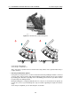
4. The flying bar is coupled with the enclosure and fixed with pins
5. Set the angle between the flying bar and the first enclosure
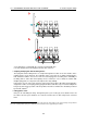
• Coupling the flying bar with the lifting device
The flying bar and the lifting device are coupled through the insertion of 16 mm shackles in the
numbered holes on the bar itself. The indication of the correct hole to use will be provided by the
LAC simulation software. You can use from one to two flying points according to the availability of
the lifting devices and to their load capacity. Please note that, in case of wind, the solution with
multiple flying points is to be preferred to improve the array stability.
In this phase you can connect the elements of the array to their cables. We advise discharging the
weight of the cables on the flying point by tying them with a textile fibre rope, instead of letting them
hang freely: this way the position of the array will be much more similar to the simulation produced
by the LAC software
11
.
• Lifting phase starts
Now you can start lifting the array. Through this phase you need to pay close attention not to let
the cables enter the space between one enclosure and the other, as their compression could cut
them.
11
In the experimental phase we verified that the effect produced by the cable weight can be compensated by using a different
hole for the coupling with the flying bar, subtracting one hole from the value suggested by the software.
66