
User manual


6. Operating guide 6.4. INSTALLATION OF THE SYSTEM
point P and the flown array. This can be done with a laser range finder or calculated trigonometrically
using the measured distance from the Sub to point P, and the measured distance between the vertical
axis of the flown array and point P and the known height of the flown array.
In the case of the use of a rangefinder, where the result is instantaneous, if the distance between the
flown array and point P is greater than that between the Sub and point P, it will be necessary to delay
the Sub output. Likewise, if the contrary is true, it will be necessary to delay the signal of the suspended
system, therefore the MID-L/HIGH pass bands from the processor. The delay to apply to one or the other
outputs is exactly the difference in meters between the two audio paths. The Proel DSO26 processor
allows the user to input the necessary delay directly in meters, but to calculate the delay in milliseconds
it is necessary only to apply the simple mathematical formula:
∆
T =
d
SAT
− d
SUB
c
For example, if the sub is 2 meters ahead with respect to the ideal position, the value to add to the
preset delay of the processor is:
∆
T =
d
SAT
− d
SUB
c
∼
=
2
344
= 0.006 [
s]=6[ms]
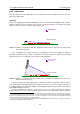
There are two possible situations, depending on the value of ∆
T : if it is positive, the sub is ahead
in phase of the flown system and must be delayed, as illustrated in figure 6.4, this is the most common
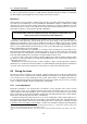
situation as it is often necessary to position the Sub line in front of the stage; if ∆
T is negative, the
flown system is ahead in phase of the sub and must be delayed, this unusual situation is illustrated in
figure 6.5.
Figure 6.4: SUB ahead in phase; SUB must be delayed.
Figure 6.5: Flown Array ahead in phase; flown array must be delayed.
In the case where no measurement system capable of determining the phase response of the system
is available, it is necessary to stop at this point. Even when such a tool is available it is advisable to
81