INSTRUCTION MANUAL PA Zone Mixer/Amplifier AMP 120Z4 / 180Z4 / 240Z4
1. IMPORTANT SAFETY INSTRUCTIONS CAUTION: To reduce the risk of electric shock do not remove cover (or back panel). No user serviceable parts inside. Refer servicing to qualified personnel only. WARNING: To reduce the risk of fire or electric shock, do not expose this apparatus to rain or moisture. This symbol is intended to alert the user of the presence of uninsulated dangerous voltage within the product enclosure that may be of sufficient magnitude to constitute a risk of electric shock to persons.
Sentences preceded by symbol contain important safety instruction. Please read it carefully. DETAILED SAFETY INSTRUCTIONS. Water and moisture: This apparatus should not be used near water (i.e. bathtub, kitchen sink, swimming pools, etc.) Ventilation: This apparatus should be placed in a position that doesn’t interfere with correct ventilation.
Objects or liquid entry inside the unit: Be careful that no objects fall or liquid is spilled inside the unit through ventilation openings. Safe power line use: • Keep firmly the plug and the wall outlet while disconnecting the unit from AC power. • If the unit will not be used for a long period of time, please unplug the power cord from AC power outlet. • To avoid unit power cord damaging, please don’t strain the AC power cable and don’t bundle it.
• To obtain good speakers wire contacts, please tighten the screw terminals firmly. • For safety reason, don’t defeat the grounding connection. Grounding is useful for user safety. Use only connectors and accessories suggested by the manufacturer. . This unit should be placed in a rack (see INSTALLATION) and kept far from: Wet places Direct exposure to heat sources (like sun light) Non properly ventilated places Disconnect the power cord during storms or when the unit is not used.
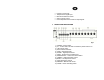
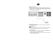
• • • • • Protection circuit LED Telephone-line signal input Bass and Treble EQ controls Output volume control Five independent level controls for input signals 3. FRONT PANEL DESCRIPTION fig. 1 1) POWER - Power switch. 2) P.I. - Power LED. This LED is lit when the power switch is on. 3) LED volume meter. 4) Zone selection switches.
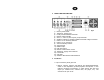
4. REAR PANEL DESCRIPTION 1) 2) 3) 4) 5) 6) 7) 8) 9) 10) 11) 12) 13) 14) 15) 16) 17) fig. 2 IEC AC power socket. Telephone - paging input. Priority function activation terminals. Monitor output terminals. Zone 1, 2, 3 and 4 (100V outputs ) output terminals. Speakers outputs for constant impedance/constant voltage connection. INPUT 1-2-3-4 sensitivity selectors. INPUT 1-2-3-4 connectors. AUX IN sensitivity selector. AUX IN inputs. MAIN IN input. PRE-OUT output. Monitor volume trimmer control.
To choose the source type to be connected, please use selectors (fig. 2 ref. 7): LINE position for AM/FM tuners, CD players etc., MIC position for dynamic microphones and PHANTOM position for condenser microphones. INPUT1 is provided of VOX function. When this input receives a signal, this signal has priority over all the other inputs; in this way only INPUT 1 audio signal is amplified. Attention - Never connect unbalanced microphones when PHANTOM power is active, this power could be damaged.
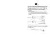
• MAIN IN and PRE OUT. MAIN IN input is connected to PRE OUT output by a jumper. It’s possible to obtain a better performance of amplified sound inserting an external unit (i.e. equalizer, processor etc.). Please see the following picture for proper wiring. • IEC AC power connection. To connect this unit to AC power outlet, please use the supplied AC linecord. (fig. 2 ref. 1). Attention Before connecting the unit to AC power, please control that the power selector (fig.2 rif.
2. Output connections Attention To prevent the risk of electric shock, never touch amplifier outputs when the amplifier is turned on. • Speakers connections. To access to speaker connection terminals remove the protection cover unscrewing the correspondent screws (fig.2 ref. 5, ref. 6). This amplifier may be used both with constant impedance speakers (4, 8, and 16 Ω) and with constant voltage speakers (25V, 70, and 100V). Make proper connections applying following instructions.
Constant voltage line If you’re using a constant voltage line, connect either the 70, or 100V to the “+” side of speaker system, and connect COM to “-“ side of the speaker (fig.2 rif.6).
− For discrete line installation (zone system), each zone is independent from the other, connect speakers terminals to COM and to the desired zone number (fig. 2 ref. 5). − If you’re using a zone selector, you won’t be able to use constant impedance speakers, since the line is set at 100 V constant voltage. − Speakers should have a transformer of the same voltage developed by the amplifier. − The speakers power sum should not exceed the amplifier maximum output power.
• MONITOR output connection This output allows you to connect a speaker (monitor), driven from the unit internal 1W amplifier, reproducing AUX IN signals. − Connection is obtained using rear panel terminals (fig. 2 ref. 4). − Output signal is set by AUX IN volume control, or by rear panel Monitor vol. trimmer (fig. 2 ref. 13). 3. GND terminal (unit grounding). This terminal allows hardware unit grounding if power socket is not “grounding” provided (fig. 2 ref. 16).
7. CHIME switch The unit has a chime built in generator, that can be activated by the front panel switch (fig. 1 ref. 13), to be used for paging beginning or end. When chime is activated it has priority over all the other signals and its volume is set by INPUT1 and MASTER controls. 6. Operations a. To turn the unit on press the POWER switch. b. To turn the unit off press the POWER switch again. c. BASS control modifies the signal lower frequencies output.
7. Technical specifications Model RMS / MAX (W) output power Constant impedance outputs Constant voltage outputs Inputs connectors Outputs connectors Frequency response Harmonic distortion Signal to noise ratio Equalization Controls AC power Rack unities Dimensions (W x H x D) Weight AMP120Z4 AMP180Z4 AMP240Z4 120 W / 150 W 180 W / 240 W 240 W / 300 W 4Ω, 8 Ω, 16Ω 25V, 70V, 100V 4 COMBO XLR / 6.
8.
The product is in compliance with Directive 89/336/EEC (Electromagnetic Compatibility) and following modifications 92/31/EEC and 93/68/EEC, as the following standards: EN 50082-1:1997, EN 55013:1990, EN 55020:1994 it is also in compliance with Directive 73/23/EEC (Low Voltage) and following modifications 93/68/EEC, as the following standard: EN 60065:1998 Proel SpA pursue a policy of continuous research and development.
PROEL S.p.A (World Headquarters - Factory) Via alla Ruenia 37/43 64027 Sant’Omero (Te) – Italy Tel: +39 0861 81241 Fax: +39 0861 887862 E-mail: info@proelgroup.com installation.proelgroup.