Sound Processor USER MANUAL www.proelgroup.
Proel Sound Processors User Manual SAFETY INSTRUCTIONS In order to avoid damage to unit hardware and electronic parts, during unit use and/or maintenance, following safety instructions must be heed. Before using the unit, please read these instructions. Follow all instructions and keep this instruction manual. - Be careful that unit operation may not cause damage to people. - Place the unit in a location protected from weather and far from water and moisture.
Proel Sound Processors User Manual Contents SAFETY INSTRUCTIONS ..............................................................................................................2 CONTENTS ....................................................................................................................................3 PROEL EXAVERB – QUICK START GUIDE .................................................................................4 FRONT PANEL.............................................................
Proel Sound Processors User Manual Proel exaverb – Quick Start Guide To connect this unit you need unbalanced (TS) ¼” cables carrying line level signals from your mixer, or other line level source, to be connected to ¼” jacks of this unit rear panel. If your sound source is monophonic, please connect the cable to “LEFT/MONO” input jack only. For stereo sound sources, use both “LEFT/MONO” and “RIGHT” jacks by connecting two discrete cables to each of the two inputs.
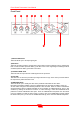
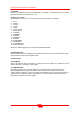
Proel Sound Processors User Manual Front Panel 1 2 3 4 6 5 7 10 8 9 11 1) INPUT LEVEL Knob This knob allows you to set input signal gain. 2) Mix Knob This knob is useful to balance original sound versus effect sound to zetaverb output. Rotating the knob counter clockwise (towards “DRY”) you’ll listen more of the original signal. Rotating the knob clockwise (towards “WET”) you’ll listen more effect. 3) OUTPUT LEVEL Knob This knob sets the output level of overall signal from the processor.
Proel Sound Processors User Manual 6) TAP LED This LED is activated only when Tap-Delay effect is recalled. The LED flashes at an inversely proportional frequency to delay time (f = 1/T). 7) Effect type selector By rotating this encoder you can choose the type of the effect among the following: 1. 2. 3. 4. 5. 6. 7. 8. 9. 10. 11. 12. 13. 14. 15. 16.
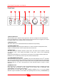
Proel Sound Processors User Manual Rear Panel 1 2 3 5 4 6 1) POWER - 9V AC power supply connector Please connect here the supplied AC power transformer. 2) Product Label 3) TAP Footswitch Jack ¼” (6.3mm.) unbalanced (TS) jack for temporary, normally open footswitch (not supplied). suggested footswitches PROEL model PFS20 or model PFS24 .
Proel Sound Processors User Manual Proel raptor – Quick Start Guide You can connect the raptor to the desired input channel insert jack of your mixer, upon your needs and/or the kind of result you’re looking for. The unit has 12 high precision notch filters for each channel (channel A and channel B). All these filters work in real time, so they can automatically detect and suppress up to 12 feedback frequencies. If you need to suppress the feedback from a single channel of your mixer (e. g.
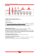
Proel Sound Processors User Manual Front Panel 1 2 3 6 5 4 10 9 8 7 11 1) INPUT LEVEL Knob This knob allows you to adjust the input signal level. Since the unit signal-to-noise ratio depends by the input signal level, in order to achieve the best sonic performances we suggest you to adjust the “INPUT LEVEL” knob on larger indent around the knob. 2) PROCESS Switch This switch allows you to activate/deactivate the feedback sound processing.
Proel Sound Processors User Manual and “FIX/VAR” (7) buttons. Please notice that rotating this knob the system will not remove the already activated notch filters. 7-11) FIX/VAR LED & Button When this LED is lit, the system is in “VAR” mode, thus when feedback frequencies are no longer detected after a certain amount of time, the system automatically resets all the activated filters.
Proel Sound Processors User Manual Table 1 – Exaverb Effects Variable Parameters Effect name Variable parameter using the “VARIATION” knob Hall Decay Rev (Time of reverb decay) Room Decay Rev (Time of reverb decay) Plate Decay Rev (Time of reverb decay) Vocal Decay Rev (Time of reverb decay) Gate Time (Time the gate circuit closes the reverb tail) Vocal echo Displacement (Selects echo type) Tap Delay Feedback (percentage of feedback delay, by “VARIATION” knob) Delay time is chosen by pressin
Proel Sound Processors User Manual Table 2 –Exaverb Effects Description Effect name Effect description Hall Simulates a large hall reverb, adopting long attack and decay times. For generic use (voice, choruses, strummed acoustic guitars, wind instruments, keyboard). Room Simulates a medium dimension room reverb, with attack and release times shorter than those of Hall. For generic use (voice, choruses, strummed acoustic guitars, wind instruments, keyboard, percussions).
Proel Sound Processors User Manual Exaverb & Raptor Techincal Specifications Inputs: 2 Unbalanced (TS) ¼” (6.3mm.) jack Outputs: 2 Unbalanced (TS) ¼” (6.3mm.) jack Footswitch inputs **: 2 Unbalanced (TS) ¼” (6.3mm.) jack Max input level: 9 dBu Max output level: 9 dBu THD+N: <0.01% @ -6 dBFS (Bypass) Signal-to-Noise Ratio: >96 dBA (Bypass) Frequency Response 20Hz-20kHz +/- 0.
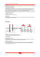
Proel Sound Processors User Manual Hook-up wiring examples (exaverb) exaverb has been designed to be used as mixer external effects unit, thus we suggest you the following hook-up. POST-FADER AUX SEND (MONO/STEREO) STEREO AUX RETURN or STEREO CHANNEL SIGNAL DIRECTION EXAVERB MIXER figure1 Note: if your mixer doesn’t have an aux send, you can use a sub-group output as send circuit and a stereo input of your mixer as effect return.
Proel Sound Processors User Manual figure 2 Hook-up and setting example (raptor) raptor has been designed to be used as mixer channel or master output processors. Thus we suggest using the following hook-up diagram. Insert Cable MIXER SEND PROCESSOR OUTPUT CHANNEL INSERT MIXER RAPTOR Figure 3 Notes It’s possible to connect another insert cable between mixer channel insert (or any other mixer channel) and raptor “B” in/out connectors, thus simultaneously using the effect on two channels.
Proel Sound Processors User Manual Front Panel Setting (raptor) In order to achieve the best possible acoustic results with your raptor, we suggest you to set “INPUT LEVEL”, and “OUTPUT LEVEL” knobs as shown in figure 4. Of course please press the “PROCESS” button in its “ON” position. figure 4 Insert (“Y” shaped) cable connection TIP = send to processor ¼” (6.3mm.) TRS jack RING = return from effect unit ¼” (6.
Proel Sound Processors User Manual 17
Proel S.p.A. (World Headquarters – Factory) Via alla Ruenia 37/43 - 64027 Sant'Omero (TE) – ITALY Tel. +39 0861 81241 - Fax +39 0861 887862 E-mail: info@proelgroup.com www.proelgroup.com REV.
Sound Processor MANUALE D'USO www.proelgroup.
Proel Sound Processors User Manual AVVERTENZE Durante le fasi di uso o manutenzione, devono essere prese alcune precauzioni onde evitare danneggiamenti alle strutture meccaniche ed elettroniche del prodotto. Prima di utilizzare il prodotto, si prega di leggere le seguenti istruzioni. Prendere visione del manuale d’uso e conservarlo per successive consultazioni. - In presenza di bambini, controllare che il prodotto non rappresenti un pericolo.
Proel Sound Processors User Manual Indice AVVERTENZE ................................................................................................................................2 INDICE ............................................................................................................................................3 PROEL EXAVERB – GUIDA RAPIDA............................................................................................4 PANNELLO FRONTALE ....................................
Proel Sound Processors User Manual Proel Exaverb – Guida Rapida Inserite il segnale di linea proveniente dal vostro mixer tramite cavo Jack da 6,3 mm sbilanciato nelle prese jack poste dietro il multieffetto. Se disponete di un segnale Monofonico, collegatelo all’ingresso “Left/Mono”, attraverso un cavo jack mono. Per segnali stereofonici, utilizzate entrambi gli ingressi “Left/Right” collegando un Jack mono a ciascuno dei due ingressi.
Proel Sound Processors User Manual Pannello Frontale 1 2 3 4 6 5 7 10 8 9 11 1)Input Level permette di regolare il guadagno del segnale in ingresso. 2)Mix permette di mixare la quantità di segnale diretto e segnale effetto all’uscita dell’exaverb. Girando la manopola verso “DRY” prevarrà il segnale diretto. Girando la manopola verso “WET” prevarrà il segnale effetto. 3)Output Level regola il livello di volume di uscita del segnale dal processore.
Proel Sound Processors User Manual 6)Led di TAP questo led è attivato esclusivamente quando è selezionato l'effetto Tap-Delay. Il led lampeggia ad una frequenza che è inversamente proporzionale al tempo di delay impostato (f = 1/T) 7)Selettore effetti ruotandolo, permette di scegliere il tipo di effetto fra i seguenti: 1. 2. 3. 4. 5. 6. 7. 8. 9. 10. 11. 12. 13. 14. 15. 16.
Proel Sound Processors User Manual Pannello Posteriore 1 2 3 5 4 6 1)Presa per alimentatore 9v AC collegate qui l’alimentatore fornito in dotazione. 2)Etichetta dati identificazione prodotto 3)Connessione per pedale TAP presa Jack 6,3 mm per connessione pedale esterno di tipo temporaneo, normalmente aperto (non in dotazione). consigliati i pedali PROEL PFS20 o PFS24 .
Proel Sound Processors User Manual Proel Raptor – Guida Rapida Potete collegare il raptor ad un qualsiasi ingresso Insert del vs. mixer, a seconda delle vostre esigenze o del tipo di risultato che vorrete ottenere. L’unità dispone di 12 filtri Notch di elevata precisione per ciascun canale (A & B) che lavorano in tempo reale, ed è in grado quindi di riconoscere ed eliminare automaticamente fino a 12 frequenze generate dall’effetto Feedback (o Larsen).
Proel Sound Processors User Manual Pannello Frontale 1 2 3 6 5 4 10 9 8 7 11 1)Input level regola la quantità di segnale in ingresso. Il rapporto segnale rumore percepito del dispositivo dipende dal livello del segnale in ingresso. Vi consigliamo di impostare la manopola di “input level” sul livello indicato dalla tacca dalle più grandi dimensioni, per ottenere risultati ottimali. 2)Process Attiva/disattiva il processamento del segnale.
Proel Sound Processors User Manual descritte nei punti 5 e 7. Si tenga presente che il semplice cambiamento delle sensibilità non rimuove i filtri notch già inseriti. 7-11)Led e tasto di Fix/Var Quando il led associato al tasto è ON siamo in modalità VAR cioè se non vengono riscontrati feedback dopo un certo tempo il sistema resetta in modo graduale i filtri notch inseriti.
Proel Sound Processors User Manual Tabella 1 – Parametri variabili degli effetti dell’unità Exaverb Nome dell’effetto Parametro modificabile tramite manopola “Variation” Hall Decay Rev (Tempo di decadimento del Riverbero) Room Decay Rev (Tempo di decadimento del Riverbero) Plate Decay Rev (Tempo di decadimento del Riverbero) Vocal Decay Rev (Tempo di decadimento del Riverbero) Gate Time (Tempo di chiusura del Riverbero) Vocal echo Displacement (Varia il tipo di eco) Tap Delay Feedback (numer
Proel Sound Processors User Manual Tabella 2 – Descrizione degli effetti dell’unità Exaverb Nome dell’effetto Descrizione dell’effetto Hall Simula il riverbero In una stanza spaziosa, con tempi di attacco e decadimento più lunghi. Per uso generico (Voce, cori, chitarre arpeggiate acustiche, strumenti a fiato, tastiera). Room Simula il riverbero in una stanza media, con tempi di attacco e decadimento più corti rispetto all’effetto Hall.
Proel Sound Processors User Manual Specifiche tecniche Exaverb/Raptor Ingressi: 2 ¼” (6.3mm) Sbilanciati Uscite: 2 ¼” (6.3mm) Sbilanciati Ingresso Pedali **: 2 ¼” (6.3mm) Sbilanciati Max livello segnale ingresso: 9 dBu Max livello segnale uscita: 9 dBu THD+N: <0.01% @ -6 dBFS (Bypass) Rapporto Segnale/Rumore >96 dBA (Bypass) Risposta in Frequenza 20Hz-20kHz +/- 0.
Proel Sound Processors User Manual Esempi di collegamento e settaggio (exaverb) L’exaverb è stato progettato con l’intento di essere utilizzato come effetto per mixer. Pertanto il collegamento consigliato è il seguente: AUX SEND MONO/STEREO POST-FADER AUX RETURN STEREO/CANALE STEREO DIREZIONE DEL SEGNALE EXAVERB MIXER fig.1 N.b.
Proel Sound Processors User Manual Esempi di collegamento e settaggio (Raptor) Il Raptor è stato progettato con l’intento di essere utilizzato come effetto per mixer. Pertanto il collegamento consigliato è il seguente: Cavo Insert MANDATA DA MIXER RITORNO DA EFFETTO INSERT CANALE MIXER RAPTOR fig.1 N.b.: è possibile collegare un ulteriore cavo insert al canale 2 (o qualsiasi altro canale) del mixer, tramite l’ingresso e l’uscita “B” del raptor, utilizzando così l’effetto su due canali del vs.
Proel Sound Processors User Manual Settaggio del pannello frontale (Raptor) Per un utilizzo ottimale del Raptor, consigliamo di posizionare le manopole “Input Level” e “Output Level” come mostrato in fig. 2. E’ necessario ricordare di posizionare il tasto “process” su ON. fig. 2 Schema di collegamento cavo insert (o cavo a “Y”) PUNTA= Mandata all’effetto JACK STEREO 6.3 mm ANELLO= Ritorno dall’effetto JACK MONO 6.3 mm N.b.
Proel Sound Processors User Manual 17
Proel S.p.A. (World Headquarters – Factory) Via alla Ruenia 37/43 - 64027 Sant'Omero (TE) – ITALY Tel. +39 0861 81241 - Fax +39 0861 887862 E-mail: info@proelgroup.com www.proelgroup.com REV.