RMW1000 Wireless Microphone System USER’S MANUAL ITALIANO ENGLISH 96MAN00082-REV.
DISPOSAL OF OLD ELECTRICAL & ELECTRONIC EQUIPMENT 3 SAFETY INSTRUCTIONS 3 IN CASE OF FAULT 3 PACKAGING, SHIPPING AND COMPLAINT 3 WARRANTY AND PRODUCTS RETURN 4 MAINTENANCE AND DISCLAIMER 4 POWER SUPPLY 4 USER’S WARNINGS AND CE CONFORMITY 5 INTRODUCTION 6 DESCRIPTION 6 RMW1000 RECEIVER 6 RMW1M HANDHELD MICROPHONE TRANSMITTER 7 RMW1H BODYPACK TRANSMITTER 8 OPERATING INSTRUCTIONS 8 BATTERY REPLACEMENT 8 WEARING THE BODYPACK RMW1H 9 SET AUTOMATICALLY A SINGLE SYSTEM 9 SET MA
DISPOSAL OF OLD ELECTRICAL & ELECTRONIC EQUIPMENT This marking shown on the product or its literature, indicates that it should not be disposed with other household wastes at the end of its working life. To prevent possible harm to the enviroment or human health from uncontrolled waste disposal, please separate this from other types of wastes and recycle it responsibly to promote the sustainable reuse of material resources.
WARRANTY AND PRODUCTS RETURN • Proel products have operating warranty and comply their specifications, as stated by manufacturer.. • Proel warrants all materials, workmanship and proper operation of this product for a period of two years from the original date of purchase.
USER’S WARNINGS AND CE CONFORMITY Changes or modifications not expressly approved by PROEL S.p.A. could void your authority to operate the equipment. LICENSING INFORMATION: • • Frequency Range of RMW1000: 551 – 581 MHz. • A ministerial license may be required to operate this equipment in certain areas. The use of this professional wireless microphone equipment in some countries could be intended for professional use, so the licensability depends on the country it operates.
INTRODUCTION Thank you for choosing this PROEL product and for your trust in our brand, synonymous of professionalism, accuracy, high quality and reliability. All our products are CE approved and designed for continuous use in professional systems. DESCRIPTION The RMW1000 Wireless Microphone is a UHF, PLL controlled, dual antenna diversity system providing a reliable and high quality signal transmission and equipped with automatic channel scan and IR sync.
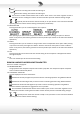
Antenna A is working and receives the radio signal. Antenna B is working and receives the radio signal. The receiver is locked and the buttons have no effect. Press “menu” and “select” together to lock or unlock the receiver. Locking the receiver and the transmitters prevents unwanted setting changes. Typically the LCD shows the channel actually in use (see further in this manual for detailed operating instructions about channel setting and frequency visualization). 11.
17. STATUS LED This LED shows the status of the transmitter: OFF: the transmitter is off or is on but muted. GREEN: the transmitter is on and operative. 18. IR After removing the battery cover, you can access the infrared port for receiving the channel setting. 19. BATTERY COMPARTMENT 20. ON – OFF – MUTE Press and hold this button for 3 seconds and you turn on the transmitter ( LED GREEN ). If you press again the button the transmitter goes in mute ( LED GREEN OFF ).
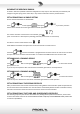
WEARING THE BODYPACK RMW1H As show in FIG.10 it’s possible to wear the bodypack to a belt, strap or dress vertically or horizontally and simply turning the spring on the other side, in any case be careful don’t fold or pull the antenna. SET AUTOMATICALLY A SINGLE SYSTEM Be sure that the transmitter is switched OFF. Press on LCD appears then press button into 5 seconds the receiver goes back to normal operation.
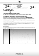
CHECK THE FREQUENCY OF THE GROUP-CHANNEL Press X 4: on LCD appears , then press and hold, the correspondent frequency remains on the display until the button is released. THE GROUP-CHANNEL FREQUENCY TABLES The TAB.1 shows the channel list and the frequency group in the range 551.000 - 581.000 MHz. SET MANUALLY THE CHANNELS TO AVOID INTERMODULATION Starting from the setup of the third radio-mic and so on a problem will occur: INTERMODULATION.
TIPS TO IMPROVE WIRELESS SYSTEM PERFORMANCE If you encounter interference or dropouts, try the following suggestions: • Choose a different receiver channel • Reposition the receiver so there is nothing obstructing a line of sight to the transmitter (including the audience) • Avoid placing transmitter and receiver where metal or other dense materials may be present • Move the receiver to the top of the equipment rack • Remove nearby sources of wireless interference, such as cell phones, two-way radios, compu
TECHNICAL SPECIFICATION RMW1000 – UHF PLL 121 Channel Receiver RF Channels 121 frequency preset RF Frequency Band UHF: 551-581 MHz RF Receiver Type PLL UHF Synthesized RF Modulation type FM (F3E) RF Sensibility -105 dBm / 12 dB SINAD RF Image/Spurious Rejection > 70 dB RF Interference Rejection > 70 dB RF Frequency Stability ± 0.005% (-10 ÷ +50 °c) THD Distortion < 0.
Connector Pin Assignments Pin 1: Tied to Ground Pin 2: Tied to +5 V Pin 3: Tied to Audio Power Supply Dimensions (WxDxH) Weight 2x1.
TRATTAMENTO DEL DISPOSITIVO ELETTRICO OD ELETTRONICO A FINE VITA ...................................... 15 AVVERTENZE PER LA SICUREZZA ........................................................................................................... 15 IN CASO DI GUASTO............................................................................................................................... 15 IMBALLAGGIO, TRASPORTO E RECLAMI .....................................................................................
TRATTAMENTO DEL DISPOSITIVO ELETTRICO OD ELETTRONICO A FINE VITA Il marchio riportato sul prodotto o sulla documentazione indica che il prodotto non deve essere smaltito con altri rifiuti domestici al termine del ciclo di vita. Per evitare eventuali danni all’ambiente si invita l’utente a separare questo prodotto da altri tipi di rifiuti e di riciclarlo in maniera responsabile per favorire il riutilizzo sostenibile delle risorse materiali.
garanzia sui prodotti venduti, attribuibili a materiali difettosi o difetti di costruzione, devono essere tempestivamente segnalati al proprio rivenditore o distributore, allegando evidenza scritta della data di acquisto e descrizione del tipo di difetto riscontrato. Sono esclusi dalla garanzia difetti causati da uso improprio o manomissione.
AVVERTENZE PER L’UTILIZZO E CONFORMITÀ CE Eventuali modifiche di qualsiasi tipo non espressamente autorizzate dalla PROEL S.p.A. possono annullare il permesso di utilizzo di questo apparecchio. INFORMATIVA SULLA LICENZA: • • RMW1000 opera nella bande di frequenze: 551 – 581 MHz. • Una licenza ministeriale è richiesta per l’uso di questo apparecchio.
INTRODUZIONE Grazie per aver scelto un prodotto PROEL e della fiducia riposta nel nostro marchio, sinonimo di professionalità, accuratezza, elevata qualità ed affidabilità. Tutti i nostri prodotti sono conformi alle normative CE per utilizzazione continua in impianti di diffusione sonora.
L’antenna B sta ricevendo il segnale radio. Il ricevitore è bloccato e i tasti non hanno nessun effetto: premere “menu” e “select” insieme per bloccare o sbloccare il ricevitore. Bloccando il ricevitore e il trasmettitore si prevengono accidentali cambiamenti d’impostazione. Tipicamente il display LCD mostra il canale attualmente in uso (vedi più avanti in questo manuale per le istruzioni dettagliate sulle impostazioni del canale e la visualizzazione della frequenza). 11.
18. IR Rimuovendo il coperchio batterie appare la porta a infrarosso per ricevere le impostazioni del canale. 19. VANO BATTERIE Ruotare il coperchio per accedere al vano batterie ed accedere alla porta a infrarosso. 20. ON –OFF- MUTE Tenendo premuto questo tasto il trasmettitore si accende , premendo ancora il tasto si può chiudere (MUTE ) o aprire (UNMUTE - LED GREEN) il microfono. Tenendo premuto il tasto per 3 secondi si può spegnere il trasmettitore . TRASMETTITORE BODYPACK RMW1H Vedi FIG.
IMPOSTAZIONE AUTOMATICA DI UN SISTEMA SINGOLO Assicurarsi che il trasmettitore sia spento. Premere su display LCD apparirà quindi premere preme il tasto entro 5 secondi il ricevitore ritorna allo stato operativo normale. : se non si Il ricevitore cercherà un canale libero nel gruppo selezionato (nota: esso cercherà una frequenza libera scartando i canali precedenti o I canali TV) quando la trova imposta il canale ACCENDERE il trasmettitore ed esporre il sensore IR al sensore IR del ricevitore, vedi FIG.
la frequenza corrispondente rimane visibile fino a quando il tasto sarà rilasciato. TABELLA GRUPPO-CANALE FREQUENZA La TAB.1 mostra la lista di canali e delle frequenze di ciascun gruppo nella gamma del modello 551.000 581.000 MHz. IMPOSTAZIONE MANUALE DEI CANALI PER EVITARE L’INTERMODULAZIONE A partire dalla impostazione del terzo sistema e successivi si verifica un problema: L’INTERMODULAZIONE.
MIGLIORARE LE PRESTAZIONI DEL SISTEMA WIRELESS In presenza di interferenze o perdite di segnale, provate a seguire le seguenti indicazioni: • Impostare un diverso canale nel ricevitore • Posizionate il ricevitore in modo che non vi siano ostacoli (pubblico incluso) sulla linea ottica verso il trasmettitore • Non collocate né il trasmettitore né il ricevitore in prossimità di oggetti metallici, scaffalature ,impalcature • Collocate il ricevitore nella parte superiore del rack per apparecchi • Rimuovete ogni
Tipo di microfono Sensibilità Microfono Alimentazione Dimensioni (DxA) Peso Dinamico Cardioide 0 / -10dB 2x1.5V AA batterie alcaline 52 x 245 mm 0.29 Kg RMW1H – Trasmettitore Bodypack 121 Canali UHF PLL Canali RF 121 frequenze preimpostate Gamma di frequenze RF UHF: 551-581 MHz Potenza RF max 10 mW Tipo di modulazione RF FM (F3E) Max deviazione RF ± 35 KHz con sistema compressore-espansore Stabilità frequenza RF ± 0.
TAB.1 GROUP CHANNEL 1 2 3 4 5 6 7 8 9 10 11 GROUP CHANNEL 1 2 3 4 5 6 7 8 9 10 11 1 2 3 4 5 6 7 557.250 560.825 562.975 564.800 566.325 567.550 569.175 571.275 572.650 574.650 575.750 557.225 560.800 562.950 564.775 566.300 567.525 569.150 571.250 572.625 574.625 575.800 556.950 558.950 560.325 562.425 564.050 565.275 566.800 568.625 570.775 574.350 575.775 556.525 557.925 559.650 560.850 563.400 564.525 566.275 567.550 569.775 557.450 559.025 561.800 562.950 565.125 566.575 567.725 569.
PROEL S.p.A. (World Headquarters - Factory) Via alla Ruenia 37/43 64027 Sant’Omero (Te) – Italy Tel: +39 0861 81241 Fax: +39 0861 887862 www.proel.