67 6HULHV +DUGZDUH 0DQXDO
Preface Thank you for purchasing Pro-face’s ST3000 Series Programmable Operator Interface (Hereafter referred to as the “ST unit”). Before operating your ST unit, be sure to read this manual to familiarize yourself with the ST unit’s operation procedures and features. NOTICE 1. Copying this manual’s contents, either in whole or in part, is prohibited without the express permission of Digital Electronics Corporation, Japan. 2. The information contained in this manual is subject to change without notice.
Essential Safety Precautions All safety-related procedures stated in this document must be followed to operate the ST correctly and safely. Be sure to read this and any related documents thoroughly to understand the correct operation and functions of the ST unit. Safety Icons Throughout this manual, these icons provide essential safety information for ST operation procedures requiring special attention.
When using the ST with transportation vehicles (trains, cars, and ships), disaster and crime prevention devices, various types of safety equipment, and medical devices that are not life-support related, use redundant and/or failsafe system designs to ensure proper reliability and safety. After the ST unit’s backlight burns out the touch panel is still active, unlike the ST unit’s “Standby Mode”.
Installation Be sure all cable connectors are securely attached to the ST unit. A loose connection may cause incorrect input or output signals. Wiring Be sure to ground the ST unit’s FG wire separately from other equipment FG lines. Also, be sure to use a grounding resistance of 100 or less and a 2mm2 or thicker wire, or your country’s applicable standard. Otherwise, electric shock or malfunctions may result. Be sure to use only the designated torque to tighten the ST unit’s terminal block screws.
Do not allow water, liquids or metal fragments to enter inside the ST unit’s case, since they can cause either a malfunction or an electric shock. The allowable pollution degree is 2. Do not operate or store the ST in locations where it can be exposed to direct sunlight, high temperatures, excessive dust, moisture or vibration. Do not operate or store the ST where chemicals evaporate, or where chemicals are present in the air.
LCD Panel Usage Precautions • The LCD panel’s liquid contains an irritant. If the panel is damaged and any of this liquid contacts your skin, immediately rinse the area with running water for at least 15 minutes. If the liquid gets in your eyes, immediately rinse your eyes with running water for at least 15 minutes and consult a doctor. • The ST unit’s LCD screen may flicker or show unevenness in the brightness of certain images or at some contrast settings.
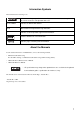
Information Symbols This manual uses the following icons: Indicates a warning or a product limitation. Be sure to follow the instructions given with this icon to ensure the safe operation of the ST. Screen Editor Indicates the GP-Pro EX software. PLC Abbreviation for Programmable Logic Controller. * Indicates useful or important supplemental information. Contains additional or useful information. SEE Indicates pages containing related information.
ST3000 Series Model Name Indication Model name A ST 3 ∗ ∗∗ - ∗ 1 - ∗∗∗ A B C D 2 ST-3200 series (3.8-inch): QVGA (320 x 240 dots) 3 ST-3300 series (5.7-inch): QVGA (320 x 240 dots) 4 ST-3400 series (7.5-inch): VGA (640 x 480 dots) 5 ST-3500 series (10.
ST3000 Series Model Names The term “ST3000” Series refers to the following ST model numbers: Series Model Product number AST-3201A AST3201-A1-D24 AST-3211A (MPI) AST3211-A1-D24 AST-3301B AST3301-B1-D24 AST-3301S AST3301-S1-D24 AST-3301T AST3301-T1-D24 AST-3302B (MPI) AST3302-B1-D24 AST-3401T AST3401-T1-D24 ST-3200 series ST-3300 series ST3000 series ST-3400 series AST3501-C1-D24 AST-3501C AST3501-C1-AF ST-3500 series AST3501-T1-D24 AST-3501T AST3501-T1-AF 9
Package Contents The following items are included in the ST unit’s package. Before using the ST, please check that all items listed here are present.
Installation prerequisites for standards DC Type • UL listed products Industrial Control Equipment • c-UL listed products Standard for Process Control Equipment refer to UL508 see [a] in the “DC Type List“ refer to CSA-C22.2 No.142 see [b] in the “DC Type List“ • DC Type List Product Model No. Registration Model No.
Be aware of the following items when building the ST into an end-use product: • The ST unit’s rear face is not approved as an enclosure. When building the ST unit into an end-use product, be sure to use an enclosure that satisfies standards as the end-use product’s overall enclosure. • The ST unit must be used indoors only. • Install and operate the ST with its front panel facing outwards. • If the ST is mounted so as to cool itself naturally, be sure to install it in a vertical panel.
Contents Preface ...................................................................................................................... 1 Essential Safety Precautions..................................................................................... 2 Information Symbols.................................................................................................. 7 About the Manuals ....................................................................................................
3.3.3 Interface Specifications .......................................................................................3-31 3.3.4 Dimensions .........................................................................................................3-33 3.4 ST-3500 Series ............................................................................................. 3-36 3.4.1 General Specifications ........................................................................................3-36 3.4.
1 Overview 1. System Design 2. Accessories This chapter describes the peripheral devices that can be connected to the ST Series units.
ST3000 Series Hardware Manual 1.1 System Design The following diagram illustrates the standard range of items that can be connected to ST3000 Series units. For host controller (PLC, etc.) connection information, refer to the “GP-Pro EX Device/PLC Connection Manual”.
Chapter 1 Overview (3) (6) RS-232C Isolation Unit CA3-ISO232-01 RS-232C Cable CA3-CBL232/5M-01 Switch setting: RS-232C Mitsubishi PLC Q-Series Link Cable CA3-CBLLNKMQ-01 (6) (6) Host Controller PLC etc.
ST3000 Series Hardware Manual (4) MPI Cable ST03-A2B-MPI21-PEE (8) Mitsubishi PLC FX-Series Connection Cable CA3-CBLFX/1M-01 CA3-CBLFX/5M-01 (9) Mitsubishi PLC A-Series Connection Cable CA3-CBLA-01 (9) (7) Host Controller PLC etc.
Chapter 1 Overview Edit Mode Peripherals ST Unit (1) USB Port USB Transfer Cable CA3-USBCB-01 USB Memory Storage *1 (Commercial type) Serial Port USB-Serial (RS-232C) Conversion Cable CA6-USB232-01 RS-232C Cable*4 (Prepared by user) Modem*1 (Commercial type) Telephone lines (2) PCMCIA Slot CF Card CA3-CFCALL/128MB-01 CA3-CFCALL/256MB-01 CA3-CFCALL/512MB-01 CA6-CFCALL/1GB-01 CA8-CFCALL/2GB-01 CF Card Adapter GP077-CFAD10 Personal Computer (Commercial type) *5 Screen Editor Software GP-Pro EX ST
ST3000 Series Hardware Manual 1.2 Accessories All accessories listed here are produced by Pro-face. Serial Interface Item Product Name Model No. Description RS-232C Cable CA3-CBL232/5M-01 (5m) Connects Mitsubishi PLC A-Series (or other host controller) to the ST. (RS-232C) RS-422 Cable CA3-CBL422/5M-01 (5m) Connects a host controller to the ST. (RS-422 / Socket Type) Mitsubishi PLC Q-Series Link Cable CA3-CBLLNKMQ-01 (5m) Connects Mitsubishi PLC Q-Series (or other host controller) to the ST.
Chapter 1 Overview Product Name Model No. Description MPI Cable ST03-A2B-MPI21-PFE The interface cable that establishes MPI(3.5m) communication between each of the hosts CA3-MPI-PGN-PFE(3.5m) and the ST3000 Series. CA3-MPI-PG1-PFE(3.5m) RS-232C Isolation Unit CA3-ISO232-01 Connects a host controller to the ST and provides isolation. RS-232C / RS-422 switching unit. USB Host Interface Product Name Model No.
ST3000 Series Hardware Manual Optional Items Product Name Screen Protection Sheet Model No. Corresponding ST CA6-DFS4-01 ST-3200 Series CA3-DFS6-01 ST-3300 Series PS400-DF00 ST-3400 Series CA5-DFS10-01 ST-3500 Series CA4-DCMDL-01 ST-3300 Series CA8-OPD10-01 ST-3500 Series Protective Cover Description Disposable, dirt-resistant sheet for the ST unit’s screen.
2 Part Names and Functions 1. ST-3200 Series 2. ST-3300 Series 3. ST-3400 Series 4. ST-3500 Series This chapter describes the names and functions of the ST series components.
ST3000 Series Hardware Manual 2.1 ST-3200 Series A: Status LED This LED indicates the ST’s status, e.g. power input or firmware RUN status. LED A Front ST Operation Green (lit) Normal operation (power is ON.) or OFFLINE operation. Orange (blinking) During software startup. Red (lit) Power is ON. Not lit Power is OFF. B B: Power Plug Connector E D C: USB Host Interface (USB) Bottom USB 1.1 compliant. One port for TYPE-A connector. Power supply voltage: DC5V ±5%.
Chapter 2 Part Names and Functions 2.2 ST-3300 Series A: Status LED This LED indicates the ST’s status, e.g. power input or firmware RUN status. LED A Front ST Operation Green (lit) Normal operation (power is ON.) or OFFLINE operation. Orange (blinking) During software startup. Red (lit) Power is ON. Not lit Power is OFF. B: Power Plug Connector C C: USB Host Interface (USB) D USB 1.1 compliant. One port for TYPE-A connector. B E Power supply voltage: DC5V ±5%.
ST3000 Series Hardware Manual 2.3 ST-3400 Series A: Status LED This LED indicates the ST’s status, e.g. power input or firmware RUN status. LED A Front ST Operation Green (lit) Normal operation (power is ON.) or OFFLINE operation. Orange (blinking) During software startup. Red (lit) Power is ON. Not lit Power is OFF. B: CF Card Access Lamp This lamp light up when CF card is inserted and CF card cover is closed.
Chapter 2 Part Names and Functions F G H F: USB Host Interface (USB) USB 1.1 compliant. One port for TYPE-A connector. Power supply voltage: DC5V ±5%. Maximum output current: 500mA Maximum communication distance: 5m Interfaces to transfer cable, USB-compatible printer, and other compatible devices. G: CF Card Cover The CF Card I/F and DIP Switches are located in the CF Card Cover opening. This cover must be closed when accessing the CF Card.
ST3000 Series Hardware Manual 2.4 ST-3500 Series The following images of an AST-3501T (AC type) Series unit. A: Status LED This LED indicates the ST’s status, e.g. power input or firmware RUN status. LED A Front C E H Green (lit) Normal operation (power is ON.) or OFFLINE operation. Orange (blinking) During software startup. Red (lit) Power is ON. Not lit Power is OFF. B: USB Host Interface (USB) USB 1.1 compliant. One port for the TYPE-A Connector. Power supply voltage: DC5V ±5%.
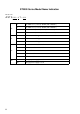
Chapter 2 Part Names and Functions H: DIP Switches ON 1 DIP Switches 2 3 4 Function ON OFF 1 Start up from CF Card Enabled Disabled 2* Forced transfer mode Forced Transfer Mode: ON Forced Transfer Mode: OFF 3 Reserved 4 Simulate cover closed, allowing card to be read even if cover open Enabled Disabled Note CF Card with startup data required Constantly OFF Used when CF Card cover is damaged * When the unit turns ON with DIP switch 2 ON, the unit starts in transfer mode.
ST3000 Series Hardware Manual 2-8
3 Specifications 1. ST-3200 Series 2. ST-3300 Series 3. ST-3400 Series 4. ST-3500 Series This chapter describes the general specifications, functions, interfaces, and external drawings of the ST.
ST3000 Series Hardware Manual 3.1 ST-3200 Series 3.1.1 General Specifications Power Supply Electrical Specifications Input Voltage DC24V Rated Voltage DC19.2 to 28.8V Allowable Voltage Drop 2ms (max.) Power Consumption 13W (max.) In-Rush Current 60A (max.)*1 Voltage Endurance AC1000V 20mA for 1 minute (between charging and FG terminals) Insulation Resistance DC500V 10MΩ (min.) (between charging and FG terminals) *1. The FWHM (Full-width, half maximum) value is approximately 40µs.
Chapter 3 Specifications Installation Structural Specifications Grounding Grounding resistance of 100Ω 2mm2 or thicker wire, or your country’s applicable standard. (Same for FG and SG terminals) *1 Rating: Equivalent to IP65f NEMA #250 TYPE 4X/13 (Front surface at panel embedding) Feature size: All-in-one Installation configuration: Panel embedding Structure Cooling Method Natural air circulation Weight Approx. 0.4kg[0.9lb] max. (unit only) External Dimensions W130mm[5.12in] X H104mm[4.
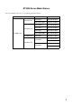
ST3000 Series Hardware Manual 3.1.2 Performance Specifications Performance Specifications AST-3201A Application *1 FLASH EPROM 6MB SRAM 320KB Interface Data Backup Serial Interface USB Host Interface AST-3211A Used lithium battery for backup memory COM1: RS-232C Asynchronous Transmission Data Length: 7 bit/8 bit Parity: none, Odd or Even Stop Bit: 1bit/2bit Data Transmission Speed: 2400 bps to 115.
Chapter 3 Specifications Display Specifications Display Type Monochrome Amber/Red LCD Resolution W320 X H240 pixels Dot pitch W0.24mm[0.01in] X H0.24mm[0.01in] Effective Display Area W78.8mm[3.10in] X H59.6mm[2.35in] Color/Shade level Black and White (8 Shades) Backlight LED (Not replaceable) Brightness control 16 levels of adjustment available via touch panel Contrast Adjustment 8 levels of adjustment available via touch panel Backlight Service Life 50000hrs.
ST3000 Series Hardware Manual 3.1.3 Interface Specifications This section describes the specifications of each interface of the ST Series unit. • The serial interface of the ST Series (except AST-3211A COM2) does not have an isolation function. When the host (PLC) unit is also not isolated, be sure to connect Pin #5 SG (Signal Ground) terminal to reduce the risk of damaging the RS-232C/RS-422/RS-485 circuit.
Chapter 3 Specifications AST-3201A Serial Interfaces (COM1) This interface is used to connect an RS-232C cable. D-Sub 9-pin plug connector is used. ST Connector XM2C-0942-502LX Interfit Bracket #4-40 inch screws are used. Recommended Cable Connector XM2D-0901 Recommended Cable Cover XM2S-0913 Recommended Jack Screw XM2Z-0073 Pin Arrangement 5 9 1 6 (ST unit side) Pin No.
ST3000 Series Hardware Manual Serial Interface (COM2) This interface is used to connect an RS-422/RS-485*1 serial cable. A D-Sub 9-pin plug connector is used. ST Connector XM2C-0942-502LX Interfit Bracket #4-40 inch screws are used. Recommended Cable Connector XM2D-0901 Recommended Cable Cover XM2S-0913 Recommended Jack Screw XM2Z-0073
Chapter 3 Specifications AST-3211A Serial Interface (COM1) This interface is used to connect an RS-232C serial cable. A D-Sub 9-pin plug connector is used. ST Connector XM2C-0942-502LX Interfit Bracket #4-40 inch screws are used. Recommended Cable Connector XM2D-0901 Recommended Cable Cover XM2S-0913 Recommended Jack Screw XM2Z-0073 Pin Arrangement 5 1 9 6 RS-232C Pin No.
ST3000 Series Hardware Manual Serial Interface (COM2) This interface is used to connect an RS-485 (MPI only) serial cable. A D-Sub 9-pin socket connector is used. ST Connector XM3B-0942-502LX Interfit Bracket #4-40 inch screws are used. Recommended Cable Connector XM2A-0901 Recommended Cable Cover XM2S-0913 Recommended Jack Screw XM2Z-0073 Pin Arrangement 1 5 6 9 (ST unit side) Pin No.
Chapter 3 Specifications 3.1.4 Dimensions The following dimensions apply to ST-3200 Series units. Installation Fasteners Attached Dimensions Unit: mm[in.] 118[4.65] Top 139.3[5.48] 40[1.57] Left side Front 92[3.62] 21.5 [0.85] 21.5 [0.85] 5[0.20] 104[4.09] 21.5[0.85] 21.5[0.85] 130[5.
ST3000 Series Hardware Manual Cable Attached Dimensions Unit: mm[in.] 83[3.27] 83[3.27] Left side 106[4.17] 84[3.31] Front Rear Right side Bottom • All the above values are designed in case of cable bending. The dimensions given here are representative values depending on the type of connection cable used. Therefore, they are all intended for reference only.
Chapter 3 Specifications Panel Cut Dimensions Unit: mm[in.] +0.04 +1 ] 118.5 -0 [4.67 -0 +0.04 +1 [3.64 ] -0 -0 r ≤ 3 [0.12] 92.5 Panel thickness area 1.6[0.06] to 5.0[0.20] Installation Fasteners Unit: mm[in.] 11 [0.43] 16[0.63] 16.6[0.65] 31[1.22] ∅10[0.
ST3000 Series Hardware Manual 3.2 ST-3300 Series 3.2.1 General Specifications Power Supply Electrical Specifications Input Voltage DC24V Rated Voltage DC19.2 to 28.8V Allowable Voltage Drop 10ms (max.) Power Consumption 18W (max.) In-Rush Current 30A (max.) Voltage Endurance AC1000V 20mA for 1 minute (between charging and FG terminals) Insulation Resistance DC500V 10MΩ (min.
Chapter 3 Specifications Installation Structural Specifications Grounding Grounding resistance of 100Ω 2mm2 or thicker wire, or your country’s applicable standard. (Same for FG and SG terminals) Structure*1 Rating: Equivalent to IP65f NEMA #250 TYPE 4X/13 (Front surface at panel embedding) Feature size: All-in-one Installation configuration: Panel embedding Cooling Method Natural air circulation Weight Approx. 1.0kg[2.2lb]max. (unit only) External Dimensions W167.5mm[6.59in] X H135mm[5.
ST3000 Series Hardware Manual 3.2.2 Performance Specifications Performance Specifications AST-3301B, AST-3301S, AST-3301T Application*1 AST-3302B FLASH EPROM 6MB SRAM 320KB Data Backup Used lithium battery for backup memory Interface COM1: RS-232C Asynchronous Transmission: Data Length: 7 bit/8 bit Parity: none, Odd or Even Stop Bit: 1bit/2bit Data Transmission Speed: 2400bps to 115.
Chapter 3 Specifications • When the message “RAAA051 Low battery” is displayed, supply power to the display unit and fully charge the battery. The battery charges within 24 hours to a level which allows backup operation. Completing a full charge requires about 96 hours (4 days). • A Lithium battery’s lifetime is: 10 years when the battery’s ambient temperature is 40°C or less. 4.1 years when the battery’s ambient temperature is 50°C or less. 1.5 years when the battery’s ambient temperature is 60°C or less.
ST3000 Series Hardware Manual Display Specifications AST-3301B Display Type AST-3302B Monochrome blue mode LCD Resolution AST-3301S AST-3301T STN Color LCD TFT Color LCD W320 X H240 pixels Dot pitch W0.36mm[0.01in] X H0.36mm[0.01in] Effective Display Area W115.2mm[4.54in] X H86.4mm[3.
Chapter 3 Specifications 3.2.3 Interface Specifications This section describes the specifications of each interface of the ST Series unit. • The serial interface of the ST Series (except AST-3302B COM2) does not have an isolation function. When the host (PLC) unit is also not isolated, be sure to connect Pin #5 SG (Signal Ground) terminal to reduce the risk of damaging the RS-232C/RS-422/RS-485 circuit.
ST3000 Series Hardware Manual Serial Interface (COM2) This interface is used to connect an RS-422/RS-485*1 serial cable. A D-Sub 9-pin plug connector is used. ST Connector XM2C-0942-502LX Interfit Bracket #4-40 inch screws are used. Recommended Cable Connector XM2D-0901 Recommended Cable Cover XM2S-0913 Recommended Jack Screw XM2Z-0073 Pin Arrangement 5 9 6 1 (ST unit side) *1 Pin No.
Chapter 3 Specifications AST-3302B Serial Interface (COM1) This interface is used to connect an RS-232C serial cable. A D-Sub 9-pin plug connector is used. ST Connector XM2C-0942-502LX Interfit Bracket #4-40 inch screws are used. Recommended Cable Connector XM2D-0901 Recommended Cable Cover XM2S-0913 Recommended Jack Screw XM2Z-0073 Pin Arrangement 5 1 9 6 RS-232C Pin No.
ST3000 Series Hardware Manual Serial Interface (COM2) This interface is used to connect an RS-485 (MPI only) serial cable. A D-Sub 9-pin socket connector is used. ST Connector XM3B-0942-502LX Interfit Bracket #4-40 inch screws are used. Recommended Cable Connector XM2A-0901 Recommended Cable Cover XM2S-0913 Recommended Jack Screw XM2Z-0073 Pin Arrangement 1 5 6 9 (ST unit side) Pin No.
Chapter 3 Specifications Dimensions The following dimensions apply to all ST-3300 Series units. Installation Fasteners Attached Dimensions Unit: mm[in.] 155.5[6.12] 65[2.56] 65[2.56] Top 59.5[2.34] 167.5[6.59] Left side Front 123[4.84] 134.4[5.29] 5[0.20] 135[5.31] 144.4[5.69] 3.2.4 Right side 50 50 [1.97] [1.
ST3000 Series Hardware Manual Cable Attached Dimensions Unit:mm[in.] 13[0.51] 24[0.94] Left side 35[1.38] Rear Right side Bottom • All the above values are designed in case of cable bending. The dimensions given here are representative values depending on the type of connection cable used. Therefore, they are all intended for reference only.
Chapter 3 Specifications Panel Cut Dimensions Unit: mm[in.] +1 -0 [6.14 +0.04 ] -0 r ≤ 3 [0.12] +1 +0.04 [4.86 ] -0 -0 156 123.5 Panel thickness area 1.6[0.06] to 5.0[0.20] Installation Fasteners Unit: mm[in.] 11 [0.43] 16[0.63] 16.6[0.65] 31[1.22] ∅10[0.
ST3000 Series Hardware Manual 3.3 ST-3400 Series 3.3.1 General Specifications Power Supply Electrical Specifications Input Voltage DC24V Rated Voltage DC19.2 to 28.8V Allowable Voltage Drop 10ms (max.) Power Consumption 22W (max.) In-Rush Current 30A (max.) Voltage Endurance AC1000V 20mA for 1 minute (between charging and FG terminals) Insulation Resistance DC500V 10MΩ (min.
Chapter 3 Specifications Installation Structural Specifications Grounding Grounding resistance of 100Ω 2mm2 or thicker wire, or your country’s applicable standard. (Same for FG and SG terminals) Structure*1 Rating: Equivalent to IP65f NEMA #250 TYPE 4X/13 (Front surface at panel embedding) Feature size: All-in-one Installation configuration: Panel embedding Cooling Method Natural air circulation Weight Approx. 1.8kg[4lb]max. (unit only) External Dimensions W215mm[8.46in] X H170mm[6.
ST3000 Series Hardware Manual 3.3.2 Performance Specifications Performance Specifications Application*1 FLASH EPROM 6MB SRAM 320KB Data Backup Used lithium battery for backup memory COM1: RS-232C Asynchronous Transmission: Data Length: 7 bit/8 bit Parity: none, Odd or Even Stop Bit: 1bit/2bit Data Transmission Speed: 2400bps to 115.
Chapter 3 Specifications • When the message “RAAA051 Low battery” is displayed, supply power to the display unit and fully charge the battery. The battery charges within 24 hours to a level which allows backup operation. Completing a full charge requires about 96 hours (4 days). • A Lithium battery’s lifetime is: 10 years when the battery’s ambient temperature is 40°C or less. 4.1 years when the battery’s ambient temperature is 50°C or less. 1.5 years when the battery’s ambient temperature is 60°C or less.
ST3000 Series Hardware Manual Display Specifications Display Type Resolution Dot pitch Effective Display Area Color/Shade level Backlight Brightness control Contrast Adjustment Backlight Service Life Text Text composition Language Fonts TFT Color LCD W640 X H480 pixels W0.237[0.01in]mm X H0.237mm[0.01in] W151.68[5.97in]mm X H113.76mm[4.48in] 256 Colors (No blink) 64 Colors (Enables blink feature) CCFL (Not replaceable) 8 levels of adjustment available via touch panel Not applicable 50000hrs.
Chapter 3 Specifications 3.3.3 Interface Specifications This section describes the specifications of each interface of the ST Series unit. • The ST unit’s serial port is not isolated. When the host (PLC) unit is also not isolated, be sure to connect Pin #5 SG (Signal Ground) terminal to reduce the risk of damaging the RS-232C/RS-422/RS-485 circuit. • When connecting an external device to the ST using the SG terminal, be sure to check that no short-circuit loop is created when you setup the system.
ST3000 Series Hardware Manual Serial Interface (COM2) This interface is used to connect an RS-422/RS-485*1 serial cable. A D-Sub 9-pin plug connector is used. ST Connector XM2C-0942-502LX Interfit Bracket #4-40 inch screws are used. Recommended Cable Connector XM2D-0901 Recommended Cable Cover XM2S-0913 Recommended Jack Screw XM2Z-0073
Chapter 3 Specifications Dimensions The following dimensions apply to all ST-3400 Series units. Installation Fasteners Attached Dimensions Unit: mm[in.] 204[8.03] 83[3.27] 83[3.27] Top 60[2.36] 215[8.46] Left side Front 83[3.27] 170.4[6.71] 159[6.26] 180.4[7.10] 5[0.20] 170[6.69] 3.3.4 Right side 83[3.
ST3000 Series Hardware Manual Cable Attached Dimensions Unit:mm[in.] 59 [2.32] 40[1.57] 36[1.42] Left side Rear Right side Bottom • All the above values are designed in case of cable bending. The dimensions given here are representative values depending on the type of connection cable used. Therefore, they are all intended for reference only.
Chapter 3 Specifications Panel Cut Dimensions Unit: mm[in.] 204.5 +1 [8.05 +0.04 ] -0 -0 +1 +0.04 159.5 -0 [6.28 -0 ] r ≤ 3 [0.12] Panel thickness area 1.6[0.06] to 10.0[0.39] Installation Fasteners Unit: mm[in.] 11[0.43] 16[0.63] 16.6[0.65] 31[1.22] ∅10[0.
ST3000 Series Hardware Manual 3.4 ST-3500 Series 3.4.1 General Specifications Power Supply Electrical Specifications DC Type AC Type Input Voltage DC24V AC100 to 240V Rated Voltage DC19.2 to 28.8V AC85 to 265V Rated frequency - 50/60Hz Rated frequency range - 40 to 72Hz Allowable Voltage Drop 10ms or less 1cycle or less (Voltage Drop interval must be 1s or more.) Power Consumption 45W or less AC100V 0.9A or less (TYP 0.48A) AC240V 0.45A or less (TYP 0.
Chapter 3 Specifications Environmental Specifications Surrounding Air Temperature Physical Storage Temperature 10 to 90% RH (Wet bulb temperature: 39°C max. - no condensation.) Storage Humidity 10 to 90% RH (Wet bulb temperature: 39°C max. - no condensation.) Dust Atmosphere Mechanical -20 to +60°C Ambient Humidity Pollution Degree Electrical 0 to +50°C 0.1mg/m3 and below (non-conductive levels) For use in Pollution Degree 2 environment.
ST3000 Series Hardware Manual Structural Specifications Grounding *1 Installation Structure Grounding resistance of 100Ω 2mm2 or thicker wire, or your country’s applicable standard. (Same for FG and SG terminals) Rating: Equivalent to IP65f NEMA #250 TYPE 4X/13 (Front surface at panel embedding) Feature size: All-in-one Installation configuration: Panel embedding Cooling Method Natural air circulation Weight Approx. 2.5kg[5.5lb] max. (unit only) External Dimensions W270.5mm[10.65in] X H212.
Chapter 3 Specifications Performance Specifications Performance Specifications Application*1 FLASH EPROM 6MB SRAM 320KB Data Backup Serial Interface Interface 3.4.2 USB Host Interface Used lithium battery for backup memory COM1: RS-232C Asynchronous Transmission: Data Length: 7 bit/8 bit Parity: none, Odd or Even Stop Bit: 1bit/2bit Data Transmission Speed: 2400bps to 115.
ST3000 Series Hardware Manual • When the message “RAAA051 Low battery” is displayed, supply power to the display unit and fully charge the battery. The battery charges within 24 hours to a level which allows backup operation. Completing a full charge requires about 96 hours (4 days). • A Lithium battery’s lifetime is: 10 years when the battery’s ambient temperature is 40°C or less. 4.1 years when the battery’s ambient temperature is 50°C or less. 1.
Chapter 3 Specifications Display Specifications Display Type AST-3501C AST-3501T Color LCD TFT Color LCD Resolution W640 X H480 pixels Dot pitch W0.33mm[0.01in] X H0.33mm[0.01in] Effective Display Area W211.2mm[8.31in] X H158.4mm[6.
ST3000 Series Hardware Manual 3.4.3 Interface Specifications This section describes the specifications of each interface of the ST Series unit. • The ST unit’s serial port is not isolated. When the host (PLC) unit is also not isolated, be sure to connect Pin #5 SG (Signal Ground) terminal to reduce the risk of damaging the RS-232C/RS-422/RS-485 circuit. • ST Series have the SG (signal ground) connection and the FG (frame ground) connection inside.
Chapter 3 Specifications Serial Interfaces Serial Interface (COM1) This interface is used to connect an RS-232C serial cable. A D-Sub 9-pin plug connector is used. ST Connector XM2C-0942-502L Interfit Bracket #4-40 inch screws are used. Recommended Cable Connector XM2D-0901 Recommended Cable Cover XM2S-0913 Recommended Jack Screw XM2Z-0073 Pin Arrangement 5 9 1 6 (ST unit side) *1 Pin No.
ST3000 Series Hardware Manual Serial Interface (COM2) This interface is used to connect an RS-422/RS-485*1 serial cable. A D-Sub 9-pin plug connector is used. ST Connector XM2C-0942-502LX Interfit Bracket #4-40 inch screws are used. Recommended Cable Connector XM2D-0901 Recommended Cable Cover XM2S-0913 Recommended Jack Screw XM2Z-0073
Chapter 3 Specifications Dimensions The following dimensions apply to all ST-3500 Series units. Installation Fasteners Attached Dimensions Unit: mm[in.] 258.5[10.18] 110[4.33] 110[4.33] Top 57[2.24] 270.5[10.65] Left side 212.5[8.37] Right side Front 110[4.33] 200.5[7.89] 5[0.20] 212.5[8.37] 222.5[8.76] 3.4.4 110[4.
ST3000 Series Hardware Manual Cable Attached Dimensions 40 [1.57] 30[1.18] Unit:mm[in.] Rear Left side Right side Power Connector 8.4[0.33] 30[1.18] Bottom The DC type unit has the power supply terminals shown above. • All the above values are designed in case of cable bending. The dimensions given here are representative values depending on the type of connection cable used. Therefore, they are all intended for reference only.
Chapter 3 Specifications Panel Cut Dimensions Unit: mm[in.] +1 +0.04 [10.20 ] -0 -0 r ≤ 3 [0.12] Panel thickness area 1.6[0.06] to 10.0[0.39] 201 +1 +0.04 [7.91 ] -0 -0 259 Installation Fasteners Unit: mm[in.] 11 [0.43] 16[0.63] 16.6[0.65] 31[1.22] ∅10[0.
ST3000 Series Hardware Manual 3-48
4 Installation and Wiring 1. Installation 2. Wiring Precautions 3. CF Card Insertion/Removal 4. USB Cable Clamp Attachment/Removal This chapter describes the installation and cable arrangement of the ST Series and its peripheral equipment.
ST3000 Series Hardware Manual 4.1 Installation This section describes the procedures and precautions for installing the ST Series units. Check the Installation Gasket’s Seal It is strongly recommended that you use the installation gasket, since it absorbs vibration in addition to repelling water. For the procedure for attaching the installation gasket, refer to “5.3 Replacing the Installation Gasket”. SEE 5.
Chapter 4 Installation and Wiring Installation Requirement • For easier maintenance, operation, and improved ventilation, be sure to install the ST at least 100 mm [3.94 in.] away from adjacent structures and other equipment. Unit: mm[im.] 100 [3.94] 100 [3.94] 100 [3.94] 100 [3.94] 100 [3.94] • 100 [3.94] 100 [3.94] Be sure that the ambient operation temperature and the ambient humidity are within their designated ranges.
ST3000 Series Hardware Manual • When installing the ST in a slanted panel, the panel face should not incline more than 30°. 30° or less • When installing the ST in a slanted panel, and the panel face inclines more than 30°, the ambient temperature must not exceed 40°C. You may need to use forced air cooling (fan, A/C) to ensure the ambient operating temperature is 40°C or below. • 4-4 When installing the ST vertically, position the unit so that the Power Input Terminal Block is also vertical.
Chapter 4 Installation and Wiring Installing the ST (1) Insert the ST into the panel cut, as shown. (2) Mount the four panel-mounting brackets Installation Panel on the right and left sides, or the top and bottom sides of the panel to secure the panel. Hook Models that have the mounting bracket holes on the sides (The drawing below is the ST-3200 series.) Models that have the mounting bracket holes on the top and bottom (The drawing below is the ST-3300 series.
ST3000 Series Hardware Manual (3) Insert each of the fasteners as shown below. Be sure to pull the fastener back until it is flush with the rear of the attachment hole. (4) Use a Phillips screwdriver to tighten each fastener screw and secure the ST in place. • Tightening the screws with too much force can damage the ST unit’s plastic case. • The torque required to tighten these screws is 0.5 N•m.
Chapter 4 Installation and Wiring 4.2 Wiring Precautions This section describes the procedures and precautions for wiring power cords. 4.2.1 Connecting the Power Cord To avoid an electric shock, prior to connecting the ST unit’s power cord terminals to the power terminal block, confirm that the ST unit’s power supply is completely turned OFF, via a breaker, or similar unit. Supplying a power voltage other than that specified will damage the power source and the ST unit.
ST3000 Series Hardware Manual When using the AC Type Power Cord Specifications Power Cord Recommended Ring Terminal *1 AC Power Cord Grounding Wire Double-insulated Wire 1.25 to 2.0mm2 (16-14 AWG) 1.25 to 2.0mm2 (16-14 AWG) V2-MS3 compatible (J.S.T. Mfg. Co., Ltd.) V2-P4 compatible (J.S.T. Mfg. Co., Ltd.) ∅4.3mm [0.17in.] or more ∅3.2mm [0.13in.] or more less than 6.0mm [0.24in.] less than 7.0mm [0.28in.] *1.
Chapter 4 Installation and Wiring When using the DC Type Power Cord Specifications Power Cord Diameter 0.75 to 2.5mm2 (18-12AWG) Conductor Type Solid or Twisted Wire 7mm[0.28in] Conductor Length • Use copper conductors only. • If the Conductor’s end (individual) wires are not twisted correctly, the end wires may either short against each other, or against an electrode.
ST3000 Series Hardware Manual Wiring When connecting the Power Cord, use the following items when performing wiring. (Items are made by Phoenix Contact.) Recommended Driver SZF 1-0.6x3.5 (1204517) Recommended Pin Terminals AI 0.75-8GY (3200519) AI 1-8RD (3200030) AI 1.5-8BK (3200043) AI 2.5-8BU (3200522) Recommended Pin Terminal Crimp Tool CRIMPFOX ZA3 (1201882) Connecting the Power Cord • Be sure to remove the connector from the ST unit prior to starting wiring.
Chapter 4 Installation and Wiring When using the ST-3500 Series (1) Confirm that the power cord is unplugged from the power supply. (2) Remove the power connector (plug) from the main unit. (3) Loosen the three screws in the center of the Power Connector (plug). (4) Strip the sheath of the power cord, twist the wire ends, insert them into the bar terminals. (5) Attach them with screws. • Use a slot screwdriver (size 0.6 x 3.5) to tighten the terminal screws.
ST3000 Series Hardware Manual 4.2.2 Connecting the Power Supply This section describes the precautions for supplying a power voltage. Twisted-pair cord Constant Voltage Transformer ST FG • If the supplied voltage exceeds the ST unit’s range, connect a constant voltage transformer. SEE Twisted-pair cord Insulating Transformer Chapter 3 Specifications (page 3-1) • Between the line and ground, select a power supply that ST FG is low in noise.
Chapter 4 Installation and Wiring 4.2.3 Grounding This section describes the precautions for grounding the ST unit. Do not use common grounding, since it can lead to an accident or machine breakdown. (a) Exclusive Grounding (BEST) • When supplying power to the ST unit, be sure to separate the Other Equipment ST input/output and power lines, as shown. [diagram (a)] • Check that the grounding resistance is 100Ω or less. • FG and SG terminals are internally connected in the ST.
ST3000 Series Hardware Manual 4.3 CF Card Insertion/Removal This section describes how to insert and remove a CF Card. When using the ST Unit and a CF Card, observe the following precautions: Prior to inserting or removing a CF Card, be sure to turn the ST unit’s CF Card ACCESS switch OFF and to confirm that the ACCESS lamp is not lit. If you do not, the CF Card’s internal data may be damaged or lost.
Chapter 4 Installation and Wiring (2) Insert the CF Card in the CF Card Slot, until the eject button is pushed forward. Eject Button (3) Close the cover. (As shown.) • Make sure that the CF Card cover is closed when accessing the CF Card. 4.3.2 Removing the CF Card Simply reverse the steps shown in the previous “Inserting CF Card” explanation. Prior to pressing the eject button to remove the CF Card, confirm that the CF Card Access LED is turned OFF. 4.3.
ST3000 Series Hardware Manual 4.4 USB Cable Clamp Attachment/Removal This clamp is used to prevent the USB cable connected to the USB Host Interface on the bottom of the ST unit from being unplugged due to vibration or other causes. 4.4.1 When using the ST-3200/3400 series Attachment (1) Before starting the procedure, lift up the tab on both sides of the USB Holder and remove the USB Cover. Tab (2) Attach the USB holder to the USB Host Interface part of the main unit.
Chapter 4 Installation and Wiring (4) Attach the USB cover to attach the USB cable. Insert the USB cover into the tab of the USB holder. ST-3200 Series ST-3400 Series USB Holder Tab USB Cover Tab USB Cover • Check the up/down orientation of the USB cover to ensure that the USB cable is secured properly. Removal (1) Lift up the tab of the USB holder and then remove the USB cover as shown below.
ST3000 Series Hardware Manual 4.4.2 When using the ST-3300 series Attachment (1) Insert the USB holder into the slot in front of the ST unit’s USB port and pull it down and forward. 2 1 (2) Pass the band of the USB cable clamp through the bridge of the USB holder. Bridge USB Holder (3) Insert the USB cable into the port. Fasten the band around the plug and secure it with the clamp.
Chapter 4 Installation and Wiring 4.4.3 When using the ST-3500 series Attachment (1) Insert the USB holder into the slot in front of the ST unit’s USB port and pull it down and forward. USB Holder 2 1 (2) Pass the band of the USB cable clamp through the bridge of the USB holder. Bridge (3) Insert the USB cable into the port. Fasten the band around the plug and secure it with the clamp.
ST3000 Series Hardware Manual Removal To remove the clamp from the USB cables, push down on the clamp strap’s clip to release it while pulling up on the clamp.
5 Maintenance 1. Cleaning the Display 2. Periodic Check Points 3. Replacing the Installation Gasket 4. Replacing the Backlight This chapter explains cautions and inspection criteria that will ensure trouble-free use of the ST.
ST3000 Series Hardware Manual 5.1 Cleaning the Display When the surface or frame of the display become dirty, soak a soft cloth in water with a neutral detergent, wring the cloth tightly, and wipe the display. • Do not use paint thinner, organic solvents, or a strong acid compound to clean the unit. • Do not use a hard or pointed object to operate the touch-screen panel, since it can damage the panel surface.
Chapter 5 Maintenance 5.2 Periodic Check Points To keep your ST unit in its best condition, please inspect the following points periodically. ST Operation Environment Is the operating temperature within the allowable range (0ºC to 50ºC)? Is the operating humidity within the specified range (10%RH to 90%RH, dry bulb temperature of 39ºC or less)? Is the operating atmosphere free of corrosive gasses? When using the ST unit inside a panel, the ambient environment refers to the interior of the panel.
ST3000 Series Hardware Manual 5.3 Replacing the Installation Gasket The installation gasket provides protection against dust and moisture. • A gasket which has been used for a long period of time may have scratches or dirt on it, and could have lost much of its water resistance. Be sure to change the gasket at least once a year, or when scratches or dirt become visible. • The ST unit installation gasket’s model number is as follows.
Chapter 5 Maintenance • The gasket must be inserted correctly into the groove for the ST’s moisture resistance to be equivalent to IP65f. • Since the gasket is flexible but not elastic, be careful not to stretch it unnecessarily, as doing so could tear the gasket. • Be sure the gasket’s seam is not inserted into any of the unit’s corners, only in the straight sections of the groove. Inserting it into a corner may lead to its eventually tearing.
ST3000 Series Hardware Manual 5.4 Replacing the Backlight The backlights of the ST3000 Series are not replaceable. Although the backlights used are a long-life type, their lifetime may be shorter than the specified period depending on the ST3000 Series operating environment. We would like to replace the displays instead of replacing the backlights. Please contact your Pro-face local distributor.