
Instruction Manual


Chapter 3 Specifications
3-31
3.3.3 Interface Specifications
This section describes the specifications of each interface of the ST Series unit.
Serial Interfaces
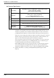
Serial Interface (COM1)
This interface is used to connect an RS-232C serial cable. A D-Sub 9-pin plug connector is used.
<ST unit side>
<Cable side>
• The ST unit’s serial port is not isolated. When the host (PLC) unit is also not
isolated, be sure to connect Pin #5 SG (Signal Ground) terminal to reduce the
risk of damaging the RS-232C/RS-422/RS-485 circuit.
• When connecting an external device to the ST using the SG terminal, be sure to
check that no short-circuit loop is created when you setup the system.
• The same type of connector is used for COM1 and COM2 of the ST. Be careful
not to mistake one for the other. Connecting them incorrectly disables
communication.
• Connecting the RS-232C isolation unit (CA3-ISO232-01) to COM1 enables isolation if
needed.
ST Connector XM2C-0942-502LX <OMRON Co.>
Interfit Bracket #4-40 inch screws are used.
Recommended Cable Connector XM2D-0901 <OMRON Co.>
Recommended Cable Cover XM2S-0913 <OMRON Co.>
Recommended Jack Screw XM2Z-0073 <OMRON Co.>
Pin
Arrangement
Pin No.
RS-232C
Signal Name Direction Meaning
1 CD Input Carrier Detect
2 RD(RXD) Input Receive Data
3 SD(TXD) Output Send Data
4 ER(DTR) Output Data Terminal Ready
5 SG - Signal Ground
6 DR(DSR) Input Data Set Ready
7 RS(RTS) Output Request to Send
8 CS(CTS) Input Send Possible
9 CI(RI)/VCC Input/-
Called status display
+5V
±5% Output 0.25A
*1
*1. The RI/VCC selection for Pin #9 is switched via software. The VCC output is not
protected against overcurrent. To prevent damage or a unit malfunction, use
only the rated current.
Shell FG -
Frame Ground
(Common with SG)
9
6
5
1
(ST unit side)