*3 6HULHV +DUGZDUH 0DQXDO
Preface Thank you for purchasing Pro-face’s GP3000 Series Programmable Operator Interface (Hereafter referred to as the “GP unit”). Before operating your GP unit, be sure to read this manual to familiarize yourself with the GP unit’s operation procedures and features. NOTICE 1. Copying this manual’s contents, either in whole or in part, is prohibited without the express permission of Digital Electronics Corporation, Japan. 2. The information contained in this manual is subject to change without notice.
Essential Safety Precautions All safety-related procedures stated in this document must be followed to operate the GP correctly and safely. Be sure to read this and any related documents thoroughly to understand the correct operation and functions of the GP unit. Safety Icons Throughout this manual, these icons provide essential safety information for GP operation procedures requiring special attention.
Design a circuit that will supply power to the GP unit’s I/O before starting up the GP. If the GP unit’s internal program enters RUN mode prior to the I/O unit’s load control power turning ON, an incorrect output (signal) or malfunction could cause an accident. Design a user program that ensures the safety of the user’s system, in the event of a GP display or control error, or either a data transmission error or power failure between the GP and a connected unit.
After the GP unit’s backlight burns out the touch panel is still active, unlike the GP unit’s “Standby Mode”. If the operator fails to notice that the backlight is burned out and touches the panel, a potentially dangerous machine operation error can occur. Therefore, do not create GP unit touch panel switches that may cause injury and/or equipment damage. If your GP unit’s backlight suddenly turns OFF, use the following steps to determine if the backlight is actually burned out.
Do not connect or disconnect Host and GP unit communication cables while the GP is turned ON. Do not replace the GP unit’s battery yourself. The GP uses a lithium battery for backing up its internal clock data and the battery may explode if it is replaced incorrectly. When replacement is required, please contact your local GP distributor.
Unit Disposal When the product is disposed of, it should be disposed of in a manner appropriate to, and in accordance with, the user country's industrial machinery disposal/recycling standards. General Safety Precautions Do not press on the GP unit’s display with excessive force or with a hard object, since it can damage the display. Also, do not press on the touch panel with a pointed object, such as the tip of a mechanical pencil or a screwdriver, since doing so can damage the touch panel.
LCD Panel Usage Precautions • The LCD panel’s liquid contains an irritant. If the panel is damaged and any of this liquid contacts your skin, immediately rinse the area with running water for at least 15 minutes. If the liquid gets in your eyes, immediately rinseyour eyes with running water for at least 15 minutes and consult a doctor. • The GP unit’s LCD screen may flicker or show unevenness in the brightness of certain images or at some contrast settings.
Information Symbols This manual uses the following icons: Indicates a warning or a product limitation. Be sure to follow the instructions given with this icon to ensure the safe operation of the GP. Screen Editor Indicates the GP-Pro EX software. PLC Abbreviation for Programmable Logic Controller. Logic program Indicates a ladder program created with the GP-Pro Ex. * Indicates useful or important supplemental information. Contains additional or useful information.
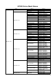
GP3000 Series Model Names Series GP-3200 series Names AGP-3200A AGP-3200T AGP-3300L AGP-3300L-D81 AGP-3300L-FN1M AGP-3300L-CA1M AGP-3300S AGP-3300S-D81 AGP-3300S-CA1M GP-3300 series AGP-3300T/U AGP-3300T-D81 AGP-3300T-FN1M AGP-3300T-CA1M AGP-3302B AGP-3301L AGP-3301S AGP-3310T AGP-3360T AGP-3400S AGP-3400S-D81 GP-3400 series AGP-3400S-CA1M AGP-3400T AGP-3400T-D81 AGP-3400T-FN1M AGP-3400T-CA1M AGP-3450T AGP-3500L AGP-3500L-D81 AGP-3500S GP3000 series AGP-3500S-D81 AGP-3500S-CA1M AGP-3500T GP-3500 seri
Package Contents The following items are included in the GP unit’s package. Before using the GP, please check that all items listed here are present.
Installation prerequisites for standards DC Type • UL listed products Industrial Control Equipment refer to UL508 see [a] in the “DC Type List“ Suitable for use in Class I, Division 2, Groups A, B, C, and D Hazardous (classified) locations, or Non-Hazardous Locations. refer to ANSI/ISA 12.12.01 see [b] in the “DC Type List“ Industrial Control Equipment refer to CSA-C22.2 No.
AC Type • UL recognized components Information Technology Equipment - Safety - Part 1 refer to UL60950-1 Suitable for use in Class I, Division 2, Groups A, B, C, and D Hazardous (classified) locations, or Non-Hazardous Locations. refer to ANSI/ISA 12.12.01 • c-UL recognized components Information Technology Equipment - Safety - Part 1 refer to CAN/CSAC22.2 No.60950-1 Suitable for use in Class I, Division 2, Groups A, B, C, and D Hazardous (classified) locations, or Non-Hazardous Locations.
Be aware of the following items when building the GP into an end-use product: • The GP unit’s rear face is not approved as an enclosure. When building the GP unit into an end-use product, be sure to use an enclosure that satisfies standards as the end-use product’s overall enclosure. • The GP unit must be used indoors only. • Install and operate the GP with its front panel facing outwards. • If the GP is mounted so as to cool itself naturally, be sure to install it in a vertical panel.
CE Marking The following units are CE marked products complying with the EMC Directive. AGP3200-A1-D24 AGP3200-T1-D24 The following units are CE marked products complying with the EMC Directive.
About Revision The nameplate on the GP has the revision number of the GP. In the example below, the asterisk, which is placed at the “A” position, shows that the revision number is “A”. When GP is Rev. A • Only for Rev.4 GP (where "*" is marked in the position of "4" on the nameplate), the "R4" mark is placed on the nameplate.
Contents Preface...................................................................................................................... 1 Essential Safety Precautions .................................................................................... 2 About the Manuals .................................................................................................... 7 Information Symbols .................................................................................................
2.4.1 CANopen Interface Unit ........................................................................................2-9 Chapter 3 Part Names and Functions 3.1 GP-3200 Series .............................................................................................. 3-2 3.2 GP-3300 Series .............................................................................................. 3-3 3.3 GP-3400 Series ..............................................................................................
4.6.4 Dimensions .........................................................................................................4-84 Chapter 5 DIO Connector 5.1 DIO Interface (Connector) .............................................................................. 5-2 5.2 Wiring to the DIO Connector........................................................................... 5-6 Chapter 6 FLEX NETWORK Connector 6.1 FLEX NETWORK Specifications ....................................................................
8.6 Installation and Removal of Function Expansion Memory ............................ 8-31 8.6.1 GP-3400 Series ..................................................................................................8-31 8.6.2 AGP-35*0T .........................................................................................................8-33 8.6.3 AGP-3500L/3500S, GP-3600/3700 Series .........................................................8-36 Chapter 9 Maintenance 9.1 Cleaning the Display .................
20
1 System Design 1. AGP-3300∗/3301∗/3310T/3360T and GP-3200/3400/3500/3600/ 3700 Series 2. AGP-3302∗ 3. DIO Board Type 4. FLEX NETWORK Board Type 5.
GP3000 Series Hardware Manual 1.1 AGP-3300∗/3301∗/3310T/3360T and GP-3200/3400/3500/3600/3700 Series The following diagram illustrates the standard range of items that can be connected to AGP-3300∗/3301∗/ 3310T/3360T and GP-3200/3400/3500/3600/3700 Series units. For host controller (PLC, etc.) connection information, refer to the “GP-Pro EX Device/PLC Connection Manual”.
Chapter 1 System Design (5) (8) RS-232C Cable CA3-CBL232/5M-01 (8) Mitsubishi PLC Q-Series Link Cable CA3-CBLLNKMQ-01 (8) Omron PLC SYSMAC Link Cable CA3-CBLSYS-01 (8) Host Controller PLC etc.
GP3000 Series Hardware Manual (6) MPI Cable ST03-A2B-MPI21-PFE Mitsubishi PLC FX-Series Connection Cable CA3-CBLFX/1M-01 CA3-CBLFX/5M-01 Mitsubishi PLC A-Series Connection Cable CA3-CBLA-01 (10) (11) (11) (9) RS-422 Cable CA3-CBL422/5M-01 COM Port Conversion Adapter CA3-ADPCOM-01 RS-422 Cable CA3-CBL422-01 (11) 2 Port Adapter Cable CA3-MDCB11 Mitsubishi PLC A, QnA, FX Series' 2 Port Adapter II GP070-MD11 Multi-Link Cable CA3-CBLMLT-01 (9) (9) Terminal Block Conversion Adapter CA3-ADPTRM-01 1-4
Chapter 1 System Design (7) (9) RS-422 Cable CA3-CBL422-01 (11) Host Controller PLC etc.
GP3000 Series Hardware Manual (7) RS-422 Cable CA3-CBL422-01 RS-485 Isolation Unit CA3-ISO485-01 (9) (11) Switch setting :4-wire (RS422) Host Controller PLC etc. 2 Port Adapter Cable CA3-MDCB11 Mitsubishi PLC A, QnA, FX Series' 2 Port Adapter II GP070-MD11 (9) Multi-Link Cable CA3-CBLMLT-01 (9) Terminal Block Conversion Adapter CA3-ADPTRM-01 RS-422 Cable CA3-CBL422-01 Online Adapter CA4-ADPONL-01 *Online adapter is required for these cases: 1:1 Communication.
Chapter 1 System Design Edit Mode Peripherals GP Unit To an Ethernet Network (1) (2) USB Port USB Transfer Cable CA3-USBCB-01 USB Memory Strage*1 (Commercial type) Serial Port USB-Serial (RS-232C) Conversion Cable CA6-USB232-01 RS-232C Cable*4 (Prepared by user) Modem*1 (Commercial type) Telephone lines (3) PCMCIA Slot CF Card CA3-CFCALL/128MB-01 CA3-CFCALL/256MB-01 CA3-CFCALL/512MB-01 CA6-CFCALL/1GB-01 CA8-CFCALL/2GB-01 CF Card Adapter GP077-CFAD10 Personal Computer (Commercial type) *5 Screen
GP3000 Series Hardware Manual 1.2 AGP-3302∗ The following diagram illustrates the standard range of items that can be connected to AGP-3302∗ units. For host controller (PLC, etc.) connection information, refer to the “GP-Pro EX Device/PLC Connection Manual”.
Chapter 1 System Design (2) (4) RS-232C Isolation Unit CA3-ISO232-01 RS-232C Cable CA3-CBL232/5M-01 Switch setting :RS-422 Mitsubishi PLC Q-Series Link Cable CA3-CBLLNKMQ-01 (4) (4) Omron PLC SYSMAC Link Cable CA3-CBLSYS-01 (4) Mitsubishi PLC Q-Series Connection Cable CA3-CBLQ-01 Host Controller PLC etc.
GP3000 Series Hardware Manual (3) MPI Cable ST03-A2B-MPI21-PEE (6) Mitsubishi PLC FX-Series Connection Cable CA3-CBLFX/1M-01 CA3-CBLFX/5M-01 (7) Mitsubishi PLC A-Series Connection Cable CA3-CBLA-01 (7) (5) RS-422 Cable CA3-CBL422/5M-01 COM Port Conversion Adapter CA3-ADPCOM-01 RS-422 Cable CA3-CBL422-01 (7) 2 Port Adapter Cable CA3-MDCB11 Mitsubishi PLC A , QnA, FX Series 2 Port Adapter II GP070-MD11 (5) Multi-Link Cable CA3-CBLMLT-01 (5) Terminal Block Conversion Adapter CA3-ADPTRM-01 RS-42
Chapter 1 System Design Edit Mode Peripherals GP Unit (1) USB Port USB Transfer Cable CA3-USBCB-01 USB Memory Strage (Commercial type) *1 Serial Port USB-Serial (RS-232C) Conversion Cable CA6-USB232-01 RS-232C Cable*4 (Prepared by user) Modem*1 (Commercial type) Telephone lines Personal Computer (Commercial type) *5 Screen Editor Software GP-Pro EX GP Interfaces (1) USB Host Interface *1 *1 For supported models, refer to Pro-face’s support site “Otasuke Pro!” (http://www.pro-face.
GP3000 Series Hardware Manual 1.3 DIO Board Type GP Unit DIO Connector CA6-DIOCNALL-01 DIO Cable (1) Various parts including I/O Unit, Indicator, LED, Sensor, Switch, etc. (Prepared by the user) GP Interfaces (1) DIO Interface 1.
Chapter 1 System Design 1.5 CANopen Board Type GP Unit CANopen slave (Commercial type*1) IO Cable (1) (Prepared by user) CANopen slave (Hybrid Terminal Block) EX Module*2 IO Cable (Prepared by user) Various types of I/O equipment Indicators, LEDs, sensors, switches, and so on Various types of I/O equipment Indicators, LEDs, sensors, switches, and so on GP Interface (1) CANopen Interface *1 For supported models, refer to Pro-face’s support site “Otasuke Pro!” (http://www.pro-face.com/otasuke/).
GP3000 Series Hardware Manual 1-14
2 Accessories 1. Accessories 2. Optional Item for the DIO Board Type 3. Optional Items for the FLEX NETWORK Board Type 4. Optional Item for the CANopen Board Type This chapter describes peripheral devices that can be connected to GP Series units.
GP3000 Series Hardware Manual 2.1 Accessories All accessories listed here are produced by Pro-face. 2.1.1 Serial Interface Item Product Name Description RS-232C Cable CA3-CBL232/5M-01 (5m) Connects Mitsubishi PLC A-Series (or other host controller) to the AGP. (RS232C) RS-422 Cable CA3-CBL422/5M-01 (5m) Connects a host controller to the GP. (RS422 / Socket Type) Mitsubishi PLC Q-Series Link Cable CA3-CBLLNKMQ-01 (5m) Connects Mitsubishi PLC Q-Series (or other host controller) to the AGP.
Chapter 2 Accessories 2.1.2 Siemens COM Port Conversion Adapter CA3-ADPSEI-01 Connects Siemens PLCs to the AGP. (for RS-485 communication) Siemens TTY Converter Cable CA6-CBLTTY/5M-01 (5m) Connects Siemens PLC S5 Series to the GP. MPI Cable ST03-A2B-MPI21-PFE (3.5m) GP3000-MPI21-PFE (3.5m) Connects a host controller to the GP for CA3-MPI-PGN-PFE (3.5m) MPI communication. CA3-MPI-PG1-PFE (3.5m) RS-232C Isolation Unit CA3-ISO232-01 Connects a host controller to the GP with provides isolation.
GP3000 Series Hardware Manual 2.1.3 CF Card Items (GP-3200 series and AGP-3302B are not available) Product Name 2.1.4 Model No. CF Card (128MB) CA3-CFCALL/128MB-01 CF Card (256MB) CA3-CFCALL/256MB-01 CF Card (512MB) CA3-CFCALL/512MB-01 CF Card (1GB) CA6-CFCALL/1GB-01 CF Card (2GB) CA8-CFCALL/2GB-01 CF Card Adapter GP077-CFAD10 Description Inserted into the GP unit’s CF Card slot. Used for read/write of CF Card data via a PC’s PCMCIA slot.
Chapter 2 Accessories 2.1.5 Maintenance Items Product Name Installation Fastener Installation Gasket Model No. Corresponding GP CA3-ATFALL-01 GP3000 Series ST400-WP01 GP-3200 Series CA3-WPG6-01 GP-3300 Series CA5-WPG8-01 GP-3400 Series CA5-WPG10-01 AGP-35*0T CA3-WPG12-01 AGP-3500L AGP-3500S GP-3600 Series CA3-WPG15-01 GP-3700 Series CA5-BLU10T-01 Description Used to install the GP into a solid panel. Provides dust and moisture resistance when GP is installed into a solid panel.
GP3000 Series Hardware Manual CA4-ATM5-01 GP-3300 Series Panel cutout adapter for mounting GP-3300 series in cutout of GP-37W2B. AGP-35*0T Panel cutout dapper for mounting GP-3500 series (TFT color LCD type only) in cutout of GP-2500/2600 series. Panel Cutout Adapter CA4-ATM10-01 *1 *2 The corresponding backlight unit depends on your GP’s revision. For details, please refer to “9.4.1 AGP-35∗0T (page9-6)”. When LED backlight is used for your GP, it is not user-replaceable.
Chapter 2 Accessories 2.2 Optional Item for the DIO Board Type 2.2.1 Maintenance Items Product Name Model No. DIO Connector CA6-DIOCNALL-01 Description Connector attached to the DIO interface. Connects an external I/O device. (Set of 5 connectors) 2.3 Optional Items for the FLEX NETWORK Board Type 2.3.1 I/O Units Product Name Model No. Description FLEX NETWORK 16-Point Input Sink Source Type I/O Unit FN-X16TS41 16-point sink/source shared I/O Unit. DC24V input signal can be connected.
GP3000 Series Hardware Manual 2.3.2 Analog Units Product Name 2.3.3 Converts 2-channel analog signals to digital signals at 12-bit resolution. FLEX NETWORK 2-Channel Digital/Analog Conversion Output Unit Converts 2-channel 12-bit digital signal to analog signal and sends output. FN-DA02AH41 FLEX NETWORK 4-Channel FN-AD04AH11 Analog/Digital Conversion Input Unit Converts 4-channel analog signals to digital signals at 12-bit resolution.
Chapter 2 Accessories 2.3.6 Maintenance Items Product Name FLEX NETWORK Connector Single-Axis Teaching Loader Cable Model No. Description Connector attached to the FLEX NETWORK interface. Connects the FLEX CA6-FNCNALL-01 NETWORK communication cable. (Set of 5 connectors) Connects the FLEX NETWORK singleFN-LD10CBL (5m) axis positioning unit and the single-axis teaching loader. 2.4 Optional Item for the CANopen Board Type 2.4.1 CANopen Interface Unit Product Name Hybrid Terminal Block Model No.
GP3000 Series Hardware Manual 2-10
3 Part Names and Functions 1. GP-3200 Series 2. GP-3300 Series 3. GP-3400 Series 4. GP-3500 Series 5. GP-3600 Series 6. GP-3700 Series This chapter describes the GP’s part name and functions of each part.
GP3000 Series Hardware Manual 3.1 GP-3200 Series A: Status LED This LED indicates the GP’s status, e.g. power input, firmware RUN status or backlight condition. Also, indicates the status of logic program execution. LED Indicates Green ON Normal operation (power is ON.) or OFFLINE operation. A Front Orange Flashing During software startup Red ON When power is turned on. OFF No Power B: Power Plug Connector B D E Bottom D: Serial Interface (COM1) RS232C/RS422/RS485 serial interface.
Chapter 3 Part Names and Functions 3.2 GP-3300 Series A: Status LED This LED indicates the GP’s status, e.g. power input, firmware RUN status or backlight condition. Also, indicates the status of logic program execution. (The logic program is disabled in the AGP-3302B/3301L/3301S. The Status LED turns on only in Operation Mode (Drawing).
GP3000 Series Hardware Manual D: Ethernet Interface (10BASE-T/100BASE-TX) The Ethernet transmission interface (10BASE-T/ 100BASE-TX). An RJ-45 type modular jack connector (8-pole) is used. The LED turns on or off to indicate the current status. (Except AGP-3301*/AGP-3302B) LED Indicates D DIO board type E F Green ON Data transmission available Green OFF No connection or subsequent transmission failure Yellow ON Data transmission is occurring.
Chapter 3 Part Names and Functions N O P Bottom (With CF Card Cover open) M: Serial Interface (COM2) AGP-3300∗/3301∗/3310T/3360T: RS422/RS485 serial interface. D-sub 9-pin socket type connector. AGP-3302∗: RS422 serial interface. D-sub 9-pin plug type connector. N: CF Card Cover The CF Card I/F and Dip Switches are located in the CF Card Cover open. This cover must be closed when accessing the CF Card. (Except AGP3302B) O: CF Card Interface Insert the CF Card in this slot.
GP3000 Series Hardware Manual S: Speaker Output Interface This interface connects a speaker. Use for mini jack connector (Φ3.5 mm). (AGP-3310T/3360T only) • The following are parts for the AGP-3310T/3360T. 1 3 % & ' . 6 4 5 2 $ - AGP-3360T Front 3-6 .
Chapter 3 Part Names and Functions 3.3 GP-3400 Series The following images of an GP-3450T Series unit. A: Status LED This LED indicates the GP’s status, e.g. power input, firmware RUN status or backlight condition. Also, indicates the status of logic program execution. A Color Indicator ON Front Green Flashing ON Red B Back Logic execution mode (when logic is enabled) OFFLINE - In operation RUN In operation STOP When power is turned on.
GP3000 Series Hardware Manual D: Auxiliary input/output /Voice Output Interface (AUX) This interface is External Reset, Alarm Output, Buzzer Output, and sound output. D E F E: Audio Input Interface (L-IN/MIC) (AGP3450T only) This interface connects a microphone. DIO board type Use for mini jack connector (Φ3.5mm). H G F: Video Input Interface (V-IN) (AGP-3450T only) This interface connects a video camera. Supports NTSC (59.9Hz) / PAL (50Hz) formats. Use for RCA Connector (75Ω).
Chapter 3 Part Names and Functions O: Ethernet Interface (LAN) The Ethernet transmission interface (10BASE-T/ 100BASE-TX). An RJ-45 type modular jack connector (8-pole) is used. The LED turns on or off to indicate the current status. O P Q LED R Bottom (With CF Card Cover open) Indicates Green ON Data transmission available Green OFF No connection or subsequent transmission failure Yellow ON Data transmission is occurring.
GP3000 Series Hardware Manual 3.4 GP-3500 Series A: Status LED This LED indicates the GP’s status, e.g. power input, firmware RUN status or backlight condition. Also, indicates the status of logic program execution. A Color Indicator ON Green Front Flashing ON Red OFFLINE - In operation RUN In operation STOP In operation Major Error ON Backlight burnout or GP malfunction*1 Flashing During software startup Please see "Chapter 9 Replacing the Backlight (page9-6)" for the details.
Chapter 3 Part Names and Functions G: Ethernet Interface (LAN) The Ethernet transmission interface (10BASE-T/ 100BASE-TX). An RJ-45 type modular jack connector (8-pole) is used. The LED turns on or off to indicate the current status. LED Indicates Green ON Data transmission available Green OFF No connection or subsequent transmission failure Yellow ON Data transmission is occurring. Yellow OFF No data transmission H: USB Host Interface (USB) (X2) Complies with USB 1.1. Uses a “ TYPE-A” connector.
GP3000 Series Hardware Manual I M: CF Card Access LED This lamp light up when CF card is inserted and CF card cover is closed. However, opening the CF card cover, in the CF card while accessing it continues to light up. J Access Lamp M N O Q R S Green ON The CF Card is inserted and the CF Card Cover is closed. Or, the CF Card is being accessed. Green OFF The CF Card is not inserted or is not being accessed.
Chapter 3 Part Names and Functions T: Dip Switches1 ON 1 2 3 4 Dip Switches Function ON OFF Note CF Card Startup Settings Startup from CF Startup from CF CF Card with startup (Controls unit startup from Card is enabled. Card is disabled. data required. the CF Card.) 1 2*1 Forced Transfer Mode 3 Booking 4 This setting controls the forced closing of the CF Card cover. *1 Forced Transfer Mode: ON Forced Transfer Mode: OFF - - Forced close enabled. Forced close disabled.
GP3000 Series Hardware Manual 3.5 GP-3600 Series The following images of an AGP- 3650T (AC model) unit. A: Status LED This LED indicates the GP’s status, e.g. power input, firmware RUN status or backlight condition. Also, indicates the status of logic program execution. A Color Indicator ON Green Front Flashing ON Red Logic execution mode (when logic is enabled) OFFLINE - In operation RUN In operation STOP When power is turned on.
Chapter 3 Part Names and Functions I G: Ethernet Interface (LAN) The Ethernet transmission interface (10BASE-T/ 100BASE-TX). An RJ-45 type modular jack connector (8-pole) is used. The LED turns on or off to indicate the current status. J L K M LED Green ON Green OFF Yellow ON N O R Q Yellow OFF S Back N O P Q R S Indicates Data transmission available No connection or subsequent transmission failure Data transmission is occurring.
GP3000 Series Hardware Manual N: Power Input Terminal Block (AC model), Power Plug Connector (DC model) O: CF Card Cover The CF Card I/F and Dip Switches are located in the CF Card Cover open. This cover must be closed when accessing the CF Card. P: Audio Input Interface (L-IN/MIC) (AGP-3650T/U only) This interface connects a microphone. Use for mini jack connector (Φ3.5mm). Q: Video Input Interface (V-IN) (AGP-3650T/U only) This interface connects a video camera. Supports NTSC (59.
Chapter 3 Part Names and Functions 3.6 GP-3700 Series The following images of an AGP-3750 (AC model) unit. A: Status LED This LED indicates the GP’s status, e.g. power input, firmware RUN status or backlight condition. Also, indicates the status of logic program execution. A Color Indicator ON Green Front Flashing ON Red Logic execution mode (when logic is enabled) OFFLINE - In operation RUN In operation STOP When power is turned on.
GP3000 Series Hardware Manual E: Expansion Unit Interface 1 Connects expansion units with communication features. F E F: VM Unit Interface The interface which connects the expansion unit which is a kind of Display manufactured by Proface. H G I J K M N O Back J L K M N O G: Auxiliary input/output /Voice Output Interface (AUX) This interface is External Reset, Alarm Output, Buzzer Output, and sound output. H: Function Expansion Memory Interface Cover Remove the cover.
Chapter 3 Part Names and Functions N: Serial Interface (COM1) RS232C/RS422/RS485 serial interface. D-sub 9-pin plug type connector. Communication method is switched via software. O: Serial Interface (COM2) RS422/RS485 serial interface. D-sub 9-pin socket type connector. P: Dip Switches ON 1 2 3 4 Dip Switches Function ON OFF 1 CF Card Startup Settings (Controls unit startup from the CF Card.) Startup from CF Card is enabled. Startup from CF Card is disabled.
GP3000 Series Hardware Manual 3-20
4 Specifications 1. GP-3200 Series 2. GP-3300 Series 3. GP-3400 Series 4. GP-3500 Series 5. GP-3600 Series 6. GP-3700 Series This chapter describes the general, functional and interface specifications of the GP as well as its dimensions.
GP3000 Series Hardware Manual 4.1 GP-3200 Series 4.1.1 General Specifications Power Supply Electrical Specifications *1 Input Voltage DC24V Rated Voltage DC19.2 to 28.8V Allowable Voltage Drop 2ms (max.) Power Consumption 13W (max.) In-Rush Current 60A (max.)*1 Voltage Endurance AC1000V 20mA for 1 minute (between charging and FG terminals) Insulation Resistance DC500V 10MΩ (min.) (between charging and FG terminals) Half width (Time duration with a current exceeding 30A): 40 µs max.
Chapter 4 Specifications Structural Specifications Grounding Structure Rating: Equivalent to IP65f NEMA #250 TYPE 4X/13 (Front surface at panel embedding) Feature size: All-in-one Installation configuration: Panel embedding Cooling Method Natural air circulation Weight Approx. 0.4kg[0.9lb] max. (unit only) External Dimensions W130.0mm[5.12in] X H104.0mm[4.09in] X D40.0mm[1.57in] Panel Cut Dimensions W118.5mm[4.67in] X H92.5mm[3.64in]*2 Panel Thickness: 1.6mm[0.06in] to 5.0mm[0.
GP3000 Series Hardware Manual 4.1.2 Performance Specifications Performance Specifications Internal Memory*1 SRAM 320KB Backup Data Interface FLASH EPROM 6MB Used lithium battery for backup memory Serial Interface COM1: RS232C/RS422/RS485 Asynchronous Transmission: Data Length: 7 bit/8 bit Parity: none, Odd or Even Stop Bit: 1bit/2bit Data transmission Speed: 2400bps to 115.2 kbps 187.5 kbps(MPI) Connector: D-SUB-9pin plug Ethernet Interface Ethernet(IEEE802.
Chapter 4 Specifications Display Specifications AGP-3200A AGP-3200T Display Type Monochrome Amber/Red LCD TFT Color LCD Resolution W320 X H240 pixels W0.24mm[0.01in] X H0.24mm[0.01in] Effective Display Area W78.8mm[3.10in] X H59.6mm[2.35in] Color/Shade level Black and White (8 Shades) 256 Colors (No blink) 64 Colors (Enables blink feature) Backlight Amber/Red LED (Not user replaceable. When replacement is required, contact your local GP distributor.) White LED (Not user replaceable.
GP3000 Series Hardware Manual 4.1.3 Interface Specifications This section describes the specifications of each interface of the GP Series unit. • For instructions on how to connect to other devices, always refer to the “GP-Pro EX Device/PLC Connection Manual”. • Always connect the #5 SG (Signal Ground) of the GP unit to the connected device, especially if the connected device is also not isolated. Failure to do so may damage the RS232C/RS422/RS485 circuit.
Chapter 4 Specifications In the case of RS232C Pin Arrangement 5 9 1 6 Pin No. 1 2 3 4 5 6 7 8 Signal Name CD RD(RXD) SD(TXD) ER(DTR) SG DR(DSR) RS(RTS) CS(CTS) 9 CI(RI)/VCC (GP unit side) Shell *1 FG RS232C Direction Meaning Input Carrier Detect Input Receive Data Output Send Data Output Data Terminal Ready Signal Ground Input Data Set Ready Output Request to Send Input Send Possible Called status display Input/+5V±5% Output 0.
GP3000 Series Hardware Manual 4.1.4 Dimensions The following dimensions apply to all GP-3200 Series units. External Dimensions Unit: mm[in.] 118[4.65] Top 40[1.57] 130[5.12] Front 4-8 92[3.62] 104[4.09] 5[0.
Chapter 4 Specifications Installation Fasteners Attached Dimensions Unit: mm[in.] 118[4.65] Top 104[4.16] 21.5 21.5 [0.85] [0.85] Left side Front 40[1.57] 92[3.62] 5[0.20] 130[5.12] 21.5 21.5 [0.85] [0.85] 139.3[5.
GP3000 Series Hardware Manual Cable Attached Dimensions Unit: mm[in.] 83[3.27] Left side 70[2.76] 84[3.31] 106[4.17] 83[3.27] Rear Right side Bottom • All the above values are designed in case of cable bending. The dimensions given here are representative values depending on the type of connection cable used. Therefore, they are all intended for reference only.
Chapter 4 Specifications Panel Cut Dimensions Unit: mm[in.] r ≤ 3 [0.12] 92.5 +1 [3.64 +0.04 ] -0 -0 +0.04 +1 ] 118.5 -0 [4.67 -0 Panel thickness area 1.6[0.06] to 5.0[0.20] • Please read “8.1 Installation” before designing the Panel Cut. Installation Fasteners Unit: mm[in.] 11[0.43] 16[0.63] 16.6[0.65] 31[1.22] Φ10[0.
GP3000 Series Hardware Manual 4.2 GP-3300 Series 4.2.1 General Specifications Electrical Specifications Power Supply AGP-3300∗/3301∗/3310T/3360T AGP-3302∗ Input Voltage DC24V Rated Voltage DC19.2 to 28.8V Allowable Voltage Drop 5ms (max.) 10ms (max.) Power Consumption 26W (max.) 18W (max.) In-Rush Current 30A (max.) Voltage Endurance AC1000V 20mA for 1 minute (between charging and FG terminals) Insulation Resistance DC500V 10MΩ (min.
Chapter 4 Specifications Structural Specifications Structure*1 • GP-3300 Series, except AGP-3300U Rating: Equivalent to IP65f NEMA #250 TYPE 4X/13 (Front surface at panel embedding) Feature size: All-in-one Installation configuration: Panel embedding • AGP-3300U Rating: IP65f NEMA #250 TYPE 1 (Front surface at panel embedding) Feature size: All-in-one Installation configuration: Panel embedding Installation Grounding Grounding resistance of 100Ω 2mm2 or thicker wire, or your country’s applicable stan
GP3000 Series Hardware Manual 4.2.2 Performance Specifications Performance Specifications GP-3300 Series (except AGP-3310T/3360T) AGP-3300∗ AGP-3301∗ *1 FLASH EPROM 6MB Internal Memory SRAM 320KB Backup Data Interface COM1: RS232C/RS422/RS485 Asynchronous Transmission: Data Length: 7 bit/8 bit Parity: none, Odd or Even Stop Bit: 1bit/2bit Data transmission Speed: 2400bps to 115.
Chapter 4 Specifications • When the message “RAAA051 Low battery” is displayed, supply power to the display unit and fully charge the battery. The battery charges within 24 hours to a level which allows backup operation. Completing a full charge requires about 96 hours (4 days). • A Lithium battery’s lifetime is: 10 years when the battery’s ambient temperature is 40°C or less. 4.1 years when the battery’s ambient temperature is 50°C or less. 1.5 years when the battery’s ambient temperature is 60°C or less.
GP3000 Series Hardware Manual AGP-3310T/3360T AGP-3310T Internal Memory*1 AGP-3360T FLASH EPROM 8MB SRAM 320KB Backup Data Use lithium battery for backup memory COM1: RS232C/RS422/RS485 Asynchronous Transmission: Data Length: 7 bit/8 bit Parity: none, Odd or Even Stop Bit: 1bit/2bit Data transmission Speed: 2400bps to 115.
Chapter 4 Specifications • When the message “RAAA051 Low battery” is displayed, supply power to the display unit and fully charge the battery. The battery charges within 24 hours to a level which allows backup operation. Completing a full charge requires about 96 hours (4 days). • A Lithium battery’s lifetime is: 10 years when the battery’s ambient temperature is 40°C or less. 4.1 years when the battery’s ambient temperature is 50°C or less. 1.5 years when the battery’s ambient temperature is 60°C or less.
GP3000 Series Hardware Manual Display Specifications AGP-3300L AGP-3301L AGP-3302B Blue-mode Monochrome LCD Display Type AGP-3300S AGP-3301S Monochrome LCD TFT Color LCD (Ultra lumiTFT Color LCD nance) W0.36mm[0.01in] X H0.36mm[0.01in] W0.18mm[0.007in] X H0.18mm[0.007in] W115.2mm[4.54in] X H86.4mm[3.40in] Color/Shade level 16 Shades Black and White 4,096 Colors (16 Shades) 65,536 Colors (No blink) 16,384 Colors (Enables blink feature) CCFL (Not user replaceable.
Chapter 4 Specifications 4.2.3 Interface Specifications This section describes the specifications of each interface of the GP Series unit. • For instructions on how to connect to other devices, always refer to the “GP-Pro EX Device/PLC Connection Manual”. • Always connect the #5 SG (Signal Ground) of the GP unit to the connected device, especially if the connected device is also not isolated. Failure to do so may damage the RS232C/RS422/RS485 circuit.
GP3000 Series Hardware Manual AGP-3300∗/3301∗/3310T/3360T Serial Interfaces (COM1) This interface is used to connect an RS232C/RS422/RS485*1cable. D-sub 9-pin plug connector is used. GP Connector XM2C-0942-502LX Interfit Bracket #4-40(UNC) Recommended Cable Connector XM2D-0901 Recommended Cable Cover XM2S-0913 Recommended Jack Screw (#4-40 UNC) XM2Z-0073 In the case of RS232C Pin Arrangement 5 9 1 6 Pin No.
Chapter 4 Specifications Serial Interface (COM2) This interface is used to connect an RS422/RS485 serial cable. A D-sub 9-pin socket connector is used. • Always connect close to the GP unit's COM port when terminating with the termination pins (TRMRX/TRMTX). GP Connector XM3B-0942-502LX Interfit Bracket #4-40(UNC) Recommended Cable Connector XM2A-0901 Recommended Cable Cover XM2S-0913
GP3000 Series Hardware Manual AGP-3302 Serial Interface (COM1) This interface is used to connect an RS232C serial cable. A D-sub 9-pin plug connector is used. GP Connector XM2C-0942-502LX Interfit Bracket #4-40(UNC) Recommended Cable Connector XM2D-0901 Recommended Cable Cover XM2S-0913 Recommended Jack Screw (#4-40 UNC) XM2Z-0073 Pin Arrangement 5 9 1 6 Pin No.
Chapter 4 Specifications Serial Interface (COM2) This interface is used to connect an RS422 serial cable. A D-sub 9-pin plug connector is used. GP Connector XM2C-0942-502LX Interfit Bracket #4-40(UNC) Recommended Cable Connector XM2D-0901 Recommended Cable Cover XM2S-0913 Recommended Jack Screw (#4-40 UNC) XM2Z-0073 Pin Arrangement 5 9 1 6 Pin No.
GP3000 Series Hardware Manual 4.2.4 Dimensions The following dimensions apply to GP-3300 Series units. External Dimensions Dimensions are the same for AGP-3300*/3301*/3302B/3310T/3360T models. Unit: mm[in.] 155.5[6.12] AGP-3300T Top 59.5[2.34] 5[0.20] 123.0[4.84] 135.0[5.31] 167.5[6.59] Front Side 155.5[6.12] AGP-3360T Top 59.5[2.34] 5[0.20] 123.0[4.84] 135.0[5.31] 167.5[6.
Chapter 4 Specifications Installation Fasteners Attached Dimensions Dimensions are the same for AGP-3300*/3301*/3302B/3310T/3360T models. Unit: mm[in.] 65[2.56] 65[2.56] AGP-3300T 59.5[2.34] Top 5[0.20] 144.4[5.69] 134.4[5.29] 167.5[6.59] Front Side 50[1.97] 50[1.97] Bottom 65[2.56] 65[2.56] AGP-3360T Top 59.5[2.34] 5[0.20] 144.4[5.69] 134.4[5.29] 167.5[6.59] Side Front 50[1.97] 50[1.
GP3000 Series Hardware Manual Cable Attached Dimensions GP-3300 dimensions with cable connected differ between AGP-3300*/3301*/3302 and AGP-3310T/3360T. AGP-3300*/3301*/3302* Unit: mm[in.] AGP-3301∗/3302B Series units are not equipped with an Ethernet interface. Front 13 [0.51] Left side 24 [0.94] 29 [1.14] Rear DIO Connector, FLEX NETWORK *1 Connector or CANopen Connector Right side Bottom (The figure shows the DIO board type unit.) *1 A 20mm [0.79 in.
Chapter 4 Specifications Unit:mm[in.] Rear 30[1.18] Power Connector Pin terminal Bottom Cable 35 [1.38] • Depending on the type of connection cable used the dimensions shown above will change. The dimensions given here are representative values and are intended for reference only.
GP3000 Series Hardware Manual AGP-3310T/3360T Unit:mm[in.] 11 [0.43] Rear Left side Bottom 40 [1.57] 100 [3.94] 23 [0.91] 42 [1.65] 72 [2.83] 74 [2.91] Right side (The figures show the AGP-3360T) • Depending on the type of connection cable used the dimensions shown above will change. The dimensions given here are representative values and are intended for reference only.
Chapter 4 Specifications Panel Cut Dimensions Unit: mm[in.] r ≤ 3 [0.12] Panel thickness area 1.6[0.06] to 5.0[0.20] +0.04 123.5 +1 [4.86 -0 ] -0 +0.04 +1 ] 156 -0 [6.14 -0 • Please read “8.1 Installation” before designing the Panel Cut. Installation Fasteners Unit: mm[in.] 11[0.43] 16[0.63] 16.6[0.65] 31[1.22] Φ10[0.
GP3000 Series Hardware Manual 4.3 GP-3400 Series 4.3.1 General Specifications Electrical Specifications Power Supply GP-3400 Series Input Voltage DC24V Rated Voltage DC19.2 to 28.8V Allowable Voltage 10ms (max.) Power Consumption 28W (max.) In-Rush Current 30A (max.) Voltage Endurance AC1000V 20mA for 1 minute (between charging and FG terminals) Insulation Resistance DC500V 10MΩ (min.
Chapter 4 Specifications Structural Specifications Grounding *1 Installation Structure Grounding resistance of 100Ω 2mm2 or thicker wire, or your country’s applicable standard. (Same for FG and SG terminals) Rating: Equivalent to IP65f NEMA #250 TYPE 4X/13 (Front surface at panel embedding) Feature size: All-in-one Installation configuration: Panel embedding Cooling Method Natural air circulation Weight Approx. 1.8kg[4.0lb]max. (unit only) 2.0kg[4.
GP3000 Series Hardware Manual 4.3.2 Performance Specifications Performance Specifications AGP-3400∗ *1 Internal Memory FLASH EPROM 16MB /8MB COM1: RS232C/RS422/RS485 Asynchronous Transmission: Data Length: 7 bit/8 bit Parity: none, Odd or Even Stop Bit: 1bit/2bit Data transmission Speed: 2400 bps to 115.2 kbps Connector: D-Sub 9-pin plug COM2: RS422/RS485 Asynchronous Transmission Data Length: 7 bit/8 bit Parity: none, Odd or Even Stop Bit: 1bit/2bit Data transmission Speed: 2400 bps to 115.
Control Memory Chapter 4 Specifications Variable Area 64 KB SRAM (uses lithium battery) Program Area 132 KB FLASH EPROM *1 User active capacity. *2 Depending on GP revision and the GP-Pro EX version, the amount of internal memory will vary. For details on how to check the revision, see “About Revision” (page 15). *3 GP revision GP-Pro EX 16MB Rev.4 is marked Ver.2.6 or higher 8MB Rev.4 is NOT marked N/A Depending on the GP-Pro EX version, the amount of internal memory will vary.
GP3000 Series Hardware Manual Display Specifications AGP-3400S Display Type AGP-3400T STN Color LCD AGP-3450T TFT Color LCD Resolution W640 X H480 pixels Dot pitch W0.237mm[0.01in] X H0.237mm[0.01in] Effective Display Area W153.7mm[6.05in] X H115.8mm[4.
Chapter 4 Specifications 4.3.3 Interface Specifications This section describes the specifications of each interface of the GP Series unit. • For instructions on how to connect to other devices, always refer to the “GP-Pro EX Device/PLC Connection Manual”. • Always connect the #5 SG (Signal Ground) of the GP unit to the connected device, especially if the connected device is also not isolated. Failure to do so may damage the RS232C/RS422/RS485 circuit.
GP3000 Series Hardware Manual In the case of RS232C Pin Arrangement 5 9 1 6 Pin No. 1 2 3 4 5 6 7 8 Signal Name CD RD(RXD) SD(TXD) ER(DTR) SG DR(DSR) RS(RTS) CS(CTS) 9 CI(RI)/VCC Shell FG (GP unit side) *1 RS232C Direction Meaning Input Carrier Detect Input Receive Data Output Send Data Output Data Terminal Ready Signal Ground Input Data Set Ready Output Request to Send Input Send Possible Called status display Input/+5V±5% Output 0.
Chapter 4 Specifications Serial Interface (COM2) This interface is used to connect an RS422/RS485 serial cable. A D-sub 9-pin socket connector is used. • Always connect close to the GP unit's COM port when terminating with the termination pins (TRMRX/TRMTX). GP Connector XM3B-0942-502LX Interfit Bracket #4-40(UNC) Recommended Cable Connector XM2A-0901 Recommended Cable Cover XM2S-0913
GP3000 Series Hardware Manual Sound Output/AUX Input/Output Interface This interface is used for external reset, alarm output, buzzer output or sound output. GP Connector S2L3.5/12/90F Applicable Terminal Block Pin Arrangement 2 1 11 12 (Cable connection side) • B2L3.
Chapter 4 Specifications Dimensions The following dimensions apply to all GP-3400 Series units. The dimensions of the AGP-3400∗ are the same. The following drawings show the AGP-3450T. External Dimensions Unit: mm[in.] 204[8.03] Top 215[8.46] 5[0.20] 60[2.36] 159[2.32] 170[6.69] 4.3.
GP3000 Series Hardware Manual Installation Fasteners Attached Dimensions Unit: mm[in.] 204[8.03] 83[3.27] 83[3.27] Top Left side Front 83[3.27] 83[3.27] Bottom 4-40 60[2.36] Right side 170.4[6.71] 180.4[7.10] 170[6.69] 5[0.20] 159[6.26 215[8.
Chapter 4 Specifications Cable Attached Dimensions Unit:mm[in.] 40[1.57] AUX Connector Power Connector 44[1.73] 29[1.14] 20[0.79] DIO Connector, FLEX NETWORK Connector or *1 CANopen Connector 28[1.10] 59[2.32] Right side Left side Rear Power Connector Cable Pin terminal 36 [1.42] Bottom (The figure shows the DIO board type unit.) *1 A 20 mm-space is necessary for the DIO/FLEX NETWORK board and a 127 mm-space for the CANopen board type.
GP3000 Series Hardware Manual Panel Cut Dimensions Unit: mm[in.] r ≤ 3 [0.12] +1 +0.04 159.5 -0 [6.28 -0 ] 204.5 +1 [8.05 +0.04 ] -0 -0 Panel thickness area 1.6[0.06] to 10.0[0.39] • Please read “8.1 Installation” before designing the Panel Cut. Installation Fasteners Unit: mm[in.] 11[0.43] 16[0.63] 16.6[0.65] Φ10[0.39] M6 4-42 31[1.
Chapter 4 Specifications 4.4 GP-3500 Series General Specifications Electrical Specifications Power Supply 4.4.1 DC model AC model Input Voltage DC24V AC100 to 240V Rated Voltage DC19.2 to 28.8V AC85 to 265V Rated frequency - 50/60Hz Rated frequency range - 40 to 72Hz Allowable Voltage 10ms or less Shorter than 1cycle (Voltage drop interval must be 1s or more) AGP-3500T AGP-3510T AGP-3550T AGP-3560T DC24V 2.08A or less (TYP 1.22A) AC100V 0.9A or less (TYP 0.58A) AC240V 0.
GP3000 Series Hardware Manual Environmental Specifications Surrounding Air Temperature Physical Storage Temperature 10 to 90% RH (Wet bulb temperature: 39°C max. - no condensation.) Storage Humidity 10 to 90% RH (Wet bulb temperature: 39°C max. - no condensation.) 0.
Chapter 4 Specifications Structural Specifications Grounding *1 Installation Structure Grounding resistance of 100Ω 2mm2 or thicker wire, or your country’s applicable standard. (Same for FG and SG terminals) Rating: Equivalent to IP65f NEMA #250 TYPE 4X/13 (Front surface at panel embedding) Feature size: All-in-one Installation configuration: Panel embedding Cooling Method Natural air circulation Weight Approx. AGP-35*0T: 2.5kg[5.5lb] max. (unit only) 2.7kg[5.
GP3000 Series Hardware Manual 4.4.2 Performance Specifications Performance Specifications AGP-3500L/3500S Internal Memory*1 *2 FLASH EPROM 16MB /8MB COM1: RS232C/RS422/RS485 Asynchronous Transmission: Data Length: 7 bit/8 bit Parity: none, Odd or Even Stop Bit: 1bit/2bit Data transmission Speed: 2400 bps to 115.2 kbps Connector: D-Sub 9-pin plug COM2: RS422/RS485 Asynchronous Transmission Data Length: 7 bit/8 bit Parity: none, Odd or Even Stop Bit: 1bit/2bit Data transmission Speed: 2400 bps to 115.
Chapter 4 Specifications Control Memory Clock Accuracy*4 ±65 seconds/ month (at room temperature) Variable Area 64 KB SRAM (uses lithium battery) Program Area 132 KB FLASH EPROM *1 User active capacity. *2 Depending on GP revision and the GP-Pro EX version, the amount of internal memory will vary. For details on how to check the revision, see “About Revision” (page 15). *3 GP revision GP-Pro EX 16MB Rev.4 is marked Ver.2.6 or higher 8MB Rev.
GP3000 Series Hardware Manual Display Specifications AGP-3500T AGP-3550T When GP Rev.5 When GP Rev.5 is NOT marked is marked AGP-3500L AGP-3500S Monochrome LCD STN Color LCD *1 Revision Display Type W800 X H600 pixels W0.33mm[0.01in] X H0.33mm[0.01in] W0.264mm[0.01in] X H0.264mm[0.01in] Effective Display Area W216.0mm[8.5in] X W215.2mm[8.43in] X H160.8mm[6.33in] H162.3mm[6.39in] Color/Shade level Black and White (16 Shades) Backlight CCFL (Not user replaceable.
Chapter 4 Specifications 4.4.3 Interface Specifications This section describes the specifications of each interface of the GP Series unit. • For instructions on how to connect to other devices, always refer to the “GP-Pro EX Device/PLC Connection Manual”. • Always connect the #5 SG (Signal Ground) of the GP unit to the connected device, especially if the connected device is also not isolated. Failure to do so may damage the RS232C/RS422/RS485 circuit.
GP3000 Series Hardware Manual In the case of RS232C Pin Arrangement 5 9 1 6 Pin No. 1 2 3 4 5 6 7 8 Signal Name CD RD(RXD) SD(TXD) ER(DTR) SG DR(DSR) RS(RTS) CS(CTS) 9 CI(RI)/VCC Shell FG (GP unit side) *1 RS232C Direction Meaning Input Carrier Detect Input Receive Data Output Send Data Output Data Terminal Ready Signal Ground Input Data Set Ready Output Request to Send Input Send Possible Called status display Input/+5V±5% Output 0.
Chapter 4 Specifications Recommended Cable Connector XM2A-0901 Recommended Cable Cover XM2S-0913 Recommended Jack Screw (#4-40 UNC) XM2Z-0073 Pin Arrangement 1 6 5 9 (GP unit side) *1 Pin No.
GP3000 Series Hardware Manual Sound Output/AUX Input/Output Interface This interface is used for external reset, alarm output, buzzer output or sound output. AGP-35*0T: S2L3.5/12/90F AGP-3500L/AGP-3500S: S2L3.5/12/180F GP Connector Applicable Terminal Block Pin Arrangement 2 1 11 12 (Cable connection side) • B2L3.
Chapter 4 Specifications Dimensions The following dimensions apply to all GP-3500 Series units. External Dimensions AGP-35*0T Unit: mm[in.] 258.5[10.18] Top 57[2.24] 200.5[7.89] 5[0.20] 212.5[8.37] 270.5[10.65] Front Right side AGP-3500L/AGP-3500S Unit: mm[in.] 301[11.85] Top 313[12.32] 56[2.20] Front 227[8.94] 5[0.20] 239[9.41] 4.4.
GP3000 Series Hardware Manual Installation Fasteners Attached Dimensions AGP-35*0T Unit: mm[in.] 258.5[10.18] 110[4.33] 110[4.33] Top 270.5[10.65] 57[2.24] Front Left side 110[4.33] 110[4.33] 212.5[8.37] 200.5[7.89] Right side Bottom 4-54 222.5[8.76] 212.5[8.37] 5[0.
Chapter 4 Specifications AGP-3500L/AGP-3500S Unit: mm[in.] 301[11.85] 130[5.12] 130[5.12] Top 313[12.32] 56[2.20] Left side Front 130[5.12] 239[9.41] 227[8.94] 249[9.80] 239[9.41] 5[0.20] Right side 130[5.
GP3000 Series Hardware Manual Cable Attached Dimensions AGP-35*0T Unit:mm[in.] *1 DIO Connector, FLEX NETWORK Connector or CANopen Connector Left side Rear 40[1.57] 25[0.98] 4[0.16] 28[1.10] 59[2.32] Right side AUX Connector 30[1.18] Power Connector 8.4[0.33] The DC type unit has the power supply terminals shown above. *1 Bottom (The figure shows the DIO board type unit.) A 20 mm-space is necessary for the DIO/FLEX NETWORK board and a 127 mm-space for the CANopen board type.
Chapter 4 Specifications AGP-3500L/AGP-3500S Unit:mm[in.] *1 DIO Connector, FLEX NETWORK Connector or CANopen Connector 12.7[0.50] 10[0.39] AUX Connector Left side Rear 26[1.02] 11[0.43] 28 [1.10] 59[2.32] Right side 30[1.18] AUX Connector 8.4[0.33] Bottom The DC type unit has the power supply terminals shown above. *1 (The figure shows the DIO board type unit.) A 20 mm-space is necessary for the DIO/FLEX NETWORK board and a 127 mm-space for the CANopen board type.
GP3000 Series Hardware Manual Panel Cut Dimensions AGP-35*0T Unit: mm[in.] r ≤ 3 [0.12] Panel thickness area 1.6[0.06] to 10.0[0.39] 201 +1 +0.04 -0 [7.91 -0 ] 259 +1 [10.20 +0.04 ] -0 -0 • Please read “8.1 Installation” before designing the Panel Cut. AGP-3500L/AGP-3500S Unit: mm[in.] 301.5 +1 [11.87 +0.04 ] -0 -0 r ≤ 3 [0.12] +0.04 +1 227.5 -0 [8.96 -0 ] Panel thickness area 1.6[0.06] to 10.0[0.39] • Please read “8.1 Installation” before designing the Panel Cut.
Chapter 4 Specifications Installation Fasteners Unit: mm[in.] 11[0.43] 16[0.63] 16.6[0.65] 31[1.22] Φ10[0.
GP3000 Series Hardware Manual 4.5 GP-3600 Series 4.5.1 General Specifications Electrical Specifications DC model AGP-3600T AGP-3650T Power Supply Revision *1 Input Voltage Rated Voltage Rated frequency Rated frequency range When GP Rev.5 is NOT marked In-Rush Current Voltage Endurance Insulation Resistance *1 AGP-3600U AGP-3650U When GP Rev.5 is marked When GP Rev.5 is NOT marked AGP-3600U AGP-3650U DC24V DC19.2 to 28.
Chapter 4 Specifications Environmental Specifications Surrounding Air Temperature Physical Storage Temperature 10 to 90% RH (Wet bulb temperature: 39°C max. - no condensation.) Storage Humidity 10 to 90% RH (Wet bulb temperature: 39°C max. - no condensation.) Dust Atmosphere Mechanical -20 to +60°C Ambient Humidity Pollution Degree Electrical 0 to 50°C 0.
GP3000 Series Hardware Manual Structural Specifications Structure*1 • GP-3600 Series, except AGP-36*0U Rating: Equivalent to IP65f NEMA #250 TYPE 4X/13 (Front surface at panel embedding) Feature size: All-in-one Installation configuration: Panel embedding • AGP-36*0U Rating: IP65f (Front surface at panel embedding) Feature size: All-in-one Installation configuration: Panel embedding Installation Grounding Grounding resistance of 100Ω 2mm2 or thicker wire, or your country’s applicable standard.
Chapter 4 Specifications Performance Specifications Performance Specifications AGP-3600* Internal Memory*1 FLASH EPROM AGP-3650* 16MB*2/8MB*2 FLASH EPROM 10MB*3/8MB*3 SRAM 320KB Backup Data Used lithium battery for backup memory COM1: RS232C/RS422/RS485 Asynchronous Transmission: Data Length: 7 bit/8 bit Parity: none, Odd or Even Stop Bit: 1bit/2bit Data transmission Speed: 2400 bps to 115.
Control Memory GP3000 Series Hardware Manual Variable Area 64 KB SRAM (uses lithium battery) Program Area 132 KB FLASH EPROM *1 User active capacity. *2 Depending on GP revision and the GP-Pro EX version, the amount of internal memory will vary. For details on how to check the revision, see “About Revision” (page 15). *3 GP revision GP-Pro EX 16MB Rev.4 is marked Ver.2.6 or higher 8MB Rev.4 is NOT marked N/A Depending on the GP-Pro EX version, the amount of internal memory will vary.
Chapter 4 Specifications Display Specifications Revision *1 AGP-3600T AGP-3650T When GP Rev.5 is NOT When GP Rev.5 is marked marked AGP-3600U-CA1M AGP-3650U TFT Color LCD (Ultra luminance) Display Type TFT Color LCD Resolution Dot pitch Effective Display Area W800 X H600 pixels W0.3075mm[0.01in] X H0.3075mm[0.01in] W248mm [9.76in] X H186.5mm[7.
GP3000 Series Hardware Manual 4.5.3 Interface Specifications This section describes the specifications of each interface of the GP Series unit. • For instructions on how to connect to other devices, always refer to the “GP-Pro EX Device/PLC Connection Manual”. • Always connect the #5 SG (Signal Ground) of the GP unit to the connected device, especially if the connected device is also not isolated. Failure to do so may damage the RS232C/RS422/RS485 circuit.
Chapter 4 Specifications In the case of RS232C Pin Arrangement 5 9 1 6 Pin No. 1 2 3 4 5 6 7 8 Signal Name CD RD(RXD) SD(TXD) ER(DTR) SG DR(DSR) RS(RTS) CS(CTS) 9 CI(RI)/VCC Shell FG (GP unit side) *1 RS232C Direction Meaning Input Carrier Detect Input Receive Data Output Send Data Output Data Terminal Ready Signal Ground Input Data Set Ready Output Request to Send Input Send Possible Called status display Input/+5V±5% Output 0.
GP3000 Series Hardware Manual Recommended Cable Connector XM2A-0901 Recommended Cable Cover XM2S-0913 Recommended Jack Screw (#4-40 UNC) XM2Z-0073 Pin Arrangement 1 6 5 9 (GP unit side) *1 4-68 Pin No.
Chapter 4 Specifications Sound Output/AUX Input/Output Interface This interface is used for external reset, alarm output, buzzer output or sound output. GP Connector S2L3.5/12/180F Applicable Terminal Block Pin Arrangement 2 1 11 12 (Cable connection side) • B2L3.
GP3000 Series Hardware Manual 4.5.4 Dimensions The following dimensions apply to all GP-3600 Series units. The dimensions of the AGP-3600∗ are the same. The following drawings show the AGP-3650T. External Dimensions Unit: mm[in.] 301[11.85] Top 239[9.41] Front 4-70 5[0.20] 56[2.20] 227[8.94] 313[12.
Chapter 4 Specifications Installation Fasteners Attached Dimensions Unit: mm[in.] 301[11.85] 130[5.12] 130[5.12] Top 313[12.32] 56[2.20] Left side Front 130[5.12] 227[8.94] 239[9.41] 249[9.80] 239[9.41] 5[0.20] Right side 130[5.
GP3000 Series Hardware Manual Cable Attached Dimensions Unit:mm[in.] *1 DIO Connector, FLEX NETWORK Connector or CANopen Connector 12.7[0.50] 10[0.39] Left side 28 [1.10] 26[1.02] 11[0.43] AUX Connector Rear 59[2.32] Right side 8.4[0.33] 30[1.18] AUX Connector Cable Bottom The DC type unit has the power supply terminals shown above. *1 (The figure shows the DIO board type unit.) A 20 mm-space is necessary for the DIO/FLEX NETWORK board and a 127 mm-space for the CANopen board type.
Chapter 4 Specifications Panel Cut Dimensions Unit: mm[in.] 301.5 +1 [11.87 +0.04 ] -0 -0 r ≤ 3 [0.12] +0.04 227.5 +1 [8.96 -0 ] -0 Panel thickness area 1.6[0.06] to 10.0[0.39] • Please read “8.1 Installation” before designing the Panel Cut. Installation Fasteners Unit: mm[in.] 11[0.43] 16[0.63] 16.6[0.65] 31[1.22] Φ10[0.
GP3000 Series Hardware Manual 4.6 GP-3700 Series 4.6.1 General Specifications Electrical Specifications AC model Input Voltage DC24V AC100 to 240V Rated Voltage DC19.2 to 28.8V AC85 to 265V Rated frequency - 50/60Hz Rated frequency range - 40 to 72Hz Allowable Voltage 10ms or less Shorter than 1cycle (Voltage drop interval must be 1s or more.) Power Consumption 50W or less AC100V 1.1A or less (TYP0.75A) AC240V 0.7A or less (TYP0.
Chapter 4 Specifications Environmental Specifications Surrounding Air Temperature Physical Storage Temperature 10 to 90% RH (Wet bulb temperature: 39°C max. - no condensation.) Storage Humidity 10 to 90% RH (Wet bulb temperature: 39°C max. - no condensation.) Dust Atmosphere Mechanical -20 to +60°C Ambient Humidity Pollution Degree Electrical 0 to 50°C 0.
GP3000 Series Hardware Manual Structurel Specifications Installation Grounding 4-76 Structure *1 Grounding resistance of 100Ω 2mm2 or thicker wire, or your country’s applicable standard. (Same for FG and SG terminals) Rating: Equivalent to IP65f NEMA #250 TYPE 4X/13 (Front surface at panel embedding) Feature size: All-in-one Installation configuration: Panel embedding Cooling Method Natural air circulation Weight Approx. 5.6kg[12.3lb]max. (unit only) External Dimensions W395mm[15.
Chapter 4 Specifications Performance Specifications Performance Specifications AGP-3750T Internal Memory*1 Backup Data Serial Interface Ethernet Interface Expansion Unit Interface Interface 4.6.2 FLASH EPROM 16MB/10MB/8MB*2 SRAM 320KB Used lithium battery for backup memory COM1: RS232C/RS422/RS485 Asynchronous Transmission: Data Length: 7 bit/8 bit Parity: none, Odd or Even Stop Bit: 1bit/2bit Data transmission Speed: 2400 bps to 115.
Control Memory GP3000 Series Hardware Manual Variable Area 64 KB SRAM (uses lithium battery) Program Area 132 KB FLASH EPROM *1 User active capacity. *2 Depending on the GP-Pro EX version and settings, the amount of internal memory will vary. GP-Pro EX *3 16MB Ver. 2.6 or higher, when the Multimedia Function is not in use. 10MB Ver. 2.6 or higher, when the Multimedia Function is in use. 8MB Ver. 2.5 or lower The GP’s internal clock has a slight error.
Chapter 4 Specifications Display Specifications AGP-3750T Revision*1 When GP Rev.5 is NOT marked Display Type When GP Rev.5 is marked TFT Color LCD Resolution W1024 X H768 pixels Dot pitch W0.297mm[0.01in] X H0.297mm[0.01in] Effective Display Area W306.2mm[12.06in] X H230.1mm[9.06in] 65,536 Colors (No blink) 16,384 Colors (Enables blink feature) Color/Shade level LED backlight (The backlight cannot be replaced by the user. The unit must be sent back for backlight replacement.
GP3000 Series Hardware Manual 4.6.3 Interface Specifications This section describes the specifications of each interface of the GP Series unit. • For instructions on how to connect to other devices, always refer to the “GP-Pro EX Device/PLC Connection Manual”. • Always connect the #5 SG (Signal Ground) of the GP unit to the connected device, especially if the connected device is also not isolated. Failure to do so may damage the RS232C/RS422/RS485 circuit.
Chapter 4 Specifications In the case of RS232C Pin Arrangement 5 9 1 6 Pin No. 1 2 3 4 5 6 7 8 Signal Name CD RD(RXD) SD(TXD) ER(DTR) SG DR(DSR) RS(RTS) CS(CTS) 9 CI(RI)/VCC Shell FG (GP unit side) *1 RS232C Direction Meaning Input Carrier Detect Input Receive Data Output Send Data Output Data Terminal Ready Signal Ground Input Data Set Ready Output Request to Send Input Send Possible Called status display Input/+5V±5% Output 0.
GP3000 Series Hardware Manual Recommended Cable Connector XM2A-0901 Recommended Cable Cover XM2S-0913 Recommended Jack Screw (#4-40 UNC) XM2Z-0073 Pin Arrangement 1 6 5 9 (GP unit side) *1 4-82 Pin No.
Chapter 4 Specifications Sound Output/AUX Input/Output Interface This interface is used for external reset, alarm output, buzzer output or sound output GP Connector S2L3.5/12/180F Applicable Terminal Block Pin Arrangement 2 1 11 12 (Cable connection side) • B2L3.
GP3000 Series Hardware Manual 4.6.4 Dimensions The following dimensions apply to all GP-3700 Series units. The following drawings show the AGP-3750T. External Dimensions Unit: mm[in.] 383[15.08] Top 60[2.36] Front 4-84 5[0.20] 282[11.10] 294[11.57] 395[15.
Chapter 4 Specifications Installation Fasteners Attached Dimensions Unit: mm[in.] 395[15.55] 383[15.08] 160[6.30] 60[2.36] Top 304[11.97] 294[11.57] Front Left side 294[11.57] 5[0.20] 405[15.94] 282[11.10] 160[6.30] Right side 160[6.3] 165[6.
GP3000 Series Hardware Manual Cable Attached Dimensions Unit: mm[in.] 12.7[0.50] 10[0.39] AUX Connector 30[1.18] Rear 8.4[0.33] 24[0.94] 10[0.39] Left side 20[0.79] Right side AUX Connector The DC type unit has the power supply terminals shown above. Bottom • All the above values are designed in case of cable bending. The dimensions given here are representative values depending on the type of connection cable used. Therefore, they are all intended for reference only.
Chapter 4 Specifications Installation Fasteners Unit: mm[in.] 11[0.43] 16[0.63] 16.6[0.65] 31[1.22] Φ10[0.
GP3000 Series Hardware Manual 4-88
5 DIO Connector 1. DIO Interface (Connector) 2. Wiring to the DIO Connector This section explains the interface specifications of the DIO board type unit (model with DIO I/F) and the wiring to the DIO Connector.
GP3000 Series Hardware Manual This section describes the DIO Connector packaged with the DIO board type unit of the GP3000 series. This connector is an accessory of the GP unit. It is also offered as an optional maintenance item by Pro-face. SEE 2.2 Optional Item for the DIO Board Type (page 2-7) • When you use the DIO board type unit of the GP3000 series, read this section in conjunction with the specifications of your GP series (Chapter 4).
Chapter 5 DIO Connector Input Specifications Rated Voltage DC 24V Maximum Allowable Voltage DC 28.8V Input Method Source/Sink Input Rated Current 5.7 mA (DC 24V) Input Resistance 4.2 kΩ ON Voltage: DC 15V or more Operation Range OFF Voltage: DC 5V or less OFF to ON: 1.5 ms or less Input Delay Time ON to OFF: 1.
GP3000 Series Hardware Manual Output Specifications (Sink type) Rated Voltage DC 24V Rated Voltage Range DC 20.4V to DC 28.8V Output Method Sink Output Maximum Load Voltage 0.2A /point, 0.4A /common Output Voltage Drop 1.5V or less Output Delay Time OFF to ON: 1ms or less ON to OFF: 1 ms or less Voltage Leakage (when OFF) 0.
Chapter 5 DIO Connector Output Specifications (Source type) Rated Voltage DC 24V Rated Voltage Range DC 20.4V to DC 28.8V Output Method Source Output Maximum Load Voltage 0.2A /point, 0.4A /common Output Voltage Drop DC 1.5V or less Output Delay Time OFF to ON: 1ms or less ON to OFF: 1 ms or less Voltage Leakage (when OFF) 0.
GP3000 Series Hardware Manual 5.2 Wiring to the DIO Connector Be sure to remove the DIO Connector from the GP unit prior to starting wiring. Failure to do so may cause an electric shock. Items Required to Wire Connectors • Screwdriver Recommended type: 1891348-1 If another manufacturer is used, be sure the part has the following dimensions: point depth: 1.5mm [0.06in.] point width: 2.4mm [0.09in.] Point shape should be DIN5264A, and meet Security Standard DN EN60900.
Chapter 5 DIO Connector (3) The adjacent wire insertion hole (round-shaped hole) will be in an open state. With the slot screwdriver inserted, insert the wire into the wire insertion hole (round-shaped hole). Screwdriver Wire Wire insertion hole (Round-shaped hole) Tool insertion hole (Square-shaped hole) (4) Remove the slot screwdriver from the tool insertion hole (square-shaped hole). The wire insertion hole (round-shaped hole) will close and the wire will be secured.
GP3000 Series Hardware Manual 5-8
6 FLEX NETWORK Connector 1. FLEX NETWORK Specifications 2. Wiring to the FLEX NETWORK Connector This section explains the interface and communication specifications of the FLEX NETWORK board type unit (model with FLEX NETWORK I/F) and the wiring to the FLEX NETWORK Connector.
GP3000 Series Hardware Manual This section describes the FLEX NETWORK Connector packaged with the FLEX NETWORK board type unit of the GP3000 series. This connector is an accessory of the GP unit. It is also offered as an optional maintenance item by Pro-face. SEE 2.3 Optional Items for the FLEX NETWORK Board Type (page 2-7) • When you use the FLEX NETWORK board type unit of the GP3000 series, read this section in conjunction with the specifications of your GP series (Chapter 4).
Chapter 6 FLEX NETWORK Connector 6.1.2 Flex Network Data Transfer Settings Communication Type 1:N Connection Method Multi Drop Transfer Distance At 6Mbps 200m per CH, at 12Mbps100m per CH Transfer Method During cyclic period, distributed transmission, Half-duplex Transfer Speed 6Mbps, 12Mbps Transfer I/F Differential method, Pulse transfer resistance Error Check Format check, bit check, CRC-12 check No. of Stations 63 stations max.
GP3000 Series Hardware Manual 6.2.2 Wiring to the FLEX NETWORK Connector Be sure to remove the FLEX NETWORK Connector from the GP unit prior to starting wiring. Failure to do so may cause an electric shock. Remove the wire’s external covering and insert the wire center strand into the opening. The applicable wire size is AWG28-16. Strip at least 7.0mm [0.28in.] of cover from the wire. Unit: mm[in.] Blue (TR+) 6 to 7 [0.24 to 0.28] White (TR-) * Do not solder end 25 to 35 [0.98 to 1.
7 CANopen Interface 1. CANopen Specifications This section explains the interface and communication specifications of the CANopen board type unit (model with CANopen I/F).
GP3000 Series Hardware Manual This section describes the CANopen Interface packaged with the CANopen board type unit of the GP3000 series. • When you use the CANopen board type unit of the GP3000 series, read this section in conjunction with the specifications of your GP series (Chapter 4). • This section describes the information specific to the CANopen board type unit of the GP3000 series.
Chapter 7 CANopen Interface 7.1 CANopen Specifications 7.1.1 CANopen Interface Connector (GP unit side) XM2C-0942-502L Recommended Cable Connector (Cable side) See page 7-5. Interfit Bracket #4-40 (UNC) Pin Arrangement 5 Signal Name 1 2 3 4 5 6 7 8 9 Shell 9 6 1 (GP Unit Side) 7.1.
GP3000 Series Hardware Manual Node 1 Node 2 Diagram 1 Node n Diagram 2 CAN_H LT CAN_L Twisted Pair Cable LT CAN_GND LT = Line Termination Diagram 1 GP Diagram 2 D-sub 9 pin (socket) Signal Pin name 2 CAN-L 3 CAN-GND 7 CAN-H Shell FG Shield GP Termination Resistance D-sub 9 pin (socket) Signal Pin name 2 CAN-L 3 CAN-GND 7 CAN-H Shell FG Shield Shield • The cable’s resistance value should be 70mΩ/m or less.
Chapter 7 CANopen Interface Model No. Recommended XM2D-0901 Cable Connector TSXCANKCDF180T CANopen Recommended Transfer Cable Manufacturer
GP3000 Series Hardware Manual 7-6
8 Installation and Wiring 1. Installation 2. Wiring Precautions 3. CF Card Insertion/Removal 4. USB Cable Clamp Attachment/Removal 5. Attaching the AUX Connector 6.
GP3000 Series Hardware Manual 8.1 Installation This section describes the procedures and precautions for installing the GP Series units. Check the Installation Gasket’s Seating It is strongly recommended that you use the installation gasket, since it absorbs vibration in addition to repelling water. For the procedure for attaching the installation gasket, refer to "9.3 Replacing the Installation Gasket". SEE 9.
Chapter 8 Installation and Wiring Installation Requirements • For easier maintenance, operation, and improved ventilation, be sure to install the GP at least 100 mm [3.94 in.] away from adjacent structures and otherequipment. Unit: mm[in.] 100 [3.94] 100[3.94] 100[3.94] 100 [3.94] • 100[3.94] 100[3.94] 100[3.94] Be sure that the surrounding air temperature and the ambient humidity are within their designated ranges.
GP3000 Series Hardware Manual • When installing the GP in a slanted panel, the panel face should not incline more than 30°. 30° or less • When installing the GP in a slanted panel, and the panel face inclines more than 30°, the ambient temperature must not exceed 40°C. You may need to use forced air cooling (fan, A/C) to ensure the ambient operating temperature is 40°C or below. • 8-4 When installing the GP vertically, position the unit so that the Power Input Terminal Block is also vertical.
Chapter 8 Installation and Wiring Installing the GP (1) Insert the GP into the panel cut, as shown. (2) Insert the installation fasteners into the GP insertion slots, at the left-and-right or top- Installation Panel and-bottom of the unit. (total: 4 slots).Only the AGP-3750T has 8 slot locations. Hook The following shows the insertion The following shows the insertion slots location that are on both left and slots location that are on the top and right sides. (GP-3200 Series) bottom sides.
GP3000 Series Hardware Manual (3) Insert each of the fasteners shown below. Be sure to pull the fastener back until it is flush with the rear of the attachment hole. (4) Use a Phillips screwdriver to tighten each fastener screw and secure the GP in place. • Tightening the screws with too much force can damage the GP unit’s plastic case. • The torque required to tighten these screws is 0.5 N•m.
Chapter 8 Installation and Wiring 8.2 Wiring Precautions This section describes the procedures and precautions for wiring power cords. 8.2.1 Connecting the Power Cord To avoid an electric shock, prior to connecting the GP unit’s power cord terminals to the power terminal block, confirm that the GP unit’s power supply is completely turned OFF, via a breaker, or similar unit. Supplying a power voltage other than that specified will damage the power source and the GP unit.
GP3000 Series Hardware Manual When the AC type Power Cord Specifications • Use copper conductors only. AC Power Cord Grounding Wire Power Cord Double-insulated Wire 1.25 to 2.0mm2 (16-14AWG) 1.25 to 2.0mm2 (16-14AWG) Recommended Ring Terminal *1 J.S.T. Mfg. Co., Ltd V2-MS3 compatible J.S.T. Mfg. Co., Ltd V2-P4 compatible Φ3.2mm or more less than 6.0mm *1 Φ4.3mm or more less than 7.
Chapter 8 Installation and Wiring When the DC Type Power Cord Specifications Power Cord Diameter 0.75 to 2.5mm2 (18-12AWG) Conductor Type Simple or Twisted Wire Conductor Length 7mm [0.28in.] • Use copper conductors only. • If the Conductor’s end (individual) wires are not twisted correctly, the end wires may either short against each other, or against an electrode.
GP3000 Series Hardware Manual Wiring When connecting the Power Cord, use the following items when performing wiring. (Items are made by Phoenix Contact.) Recommended Driver SZF 1-0.6x3.5 (1204517) Recommended Pin Terminals AI 0.75-8GY (3200519) AI 1-8RD (3200030) AI 1.5-8BK (3200043) AI 2.5-8BU (3200522) Recommended Pin Terminal Crimp Tool CRIMPFOX ZA3 (1201882) Connecting the Power Cord • Be sure to remove the connector from the GP unit prior to starting wiring.
Chapter 8 Installation and Wiring When the GP-3500/3600/3700 series is used; (1) Confirm that the power cord is unplugged from the power supply. (2) Remove the power connector (plug) from the main unit. (3) Loosen the three screws in the center of the Power Connector (plug). (4) Strip the sheath of the power cord, twist the wire ends, insert them into the bar terminals. (5) Fix them with screws. • Use a flat-blade screwdriver (Size 0.6 X 3.5) to tighten the terminal screws.
GP3000 Series Hardware Manual 8.2.2 Connecting the Power Supply This section describes the precautions for supplying a power voltage. Twisted-pair cord Constant Voltage Transformer • If the supplied voltage exceeds the GP unit’s range, GP FG connect a constant voltage transformer. SEE Chapter 4 Specifications (page 4-1) • For between the line and ground, select a power Twisted-pair cord supply that is low in noise.
Chapter 8 Installation and Wiring 8.2.3 Grounding This section describes the precautions for grounding the GP unit. Do not use common grounding, since it can lead to an accident or machine breakdown. (a) Exclusive Grounding (BEST) GP • When supplying power to the GP unit, be sure to separate the Other Equipment input/output and power lines, as shown. [diagram (a)] • Check that the grounding resistance is 100Ω or less. • FG and SG terminals are internally connected in the GP.
GP3000 Series Hardware Manual 8.2.4 Wiring Precautions To help prevent noise and interference problems, separate all control, communication and power lines by placing them in a separate ducts. Duct for I/O Signal Lines Duct for Control Lines Duct for Power Lines If different wires must be placed in the same duct, separate them with an earthed/grounded divider.
Chapter 8 Installation and Wiring 8.2.5 Installation Precautions • When you use the DIO/FLEX NETWORK board type unit of the GP3000 series, read the following installation precautions. External power failure or failure of the GP unit may cause abnormal behavior.
GP3000 Series Hardware Manual Emergency Stop Circuit Do not process emergency stop signals with a software program by inputting the signal to the GP.
Chapter 8 Installation and Wiring • After executing an internal program, the GP outputs ON/OFF information to the output devices at the same time. For example, the electromagnetic switches for forward and reverse rotation of a motor are turned on and off at the same time. Consequently, a situation may arise in which both of the main contacts of the motor circuits for the electromagnetic switches for forward and reverse rotation may turn on, causing a short-circuit of the R and T phases.
GP3000 Series Hardware Manual 8.3 CF Card Insertion/Removal This section describes how to insert and remove a CF Card. When using the GP Unit and a CF Card, observe the following precautions: Prior to inserting or removing a CF Card, be sure to turn the AGP unit’s CF Card ACCESS switch OFF and to confirm that the ACCESS lamp is not lit. If you do not, CF Card internal data may be damaged or lost.
Chapter 8 Installation and Wiring 8.3.1 Inserting the CF Card Use the following steps to insert the CF Card in the GP. (1) Pull the CF Card Cover frontward and then open it upward. (2) Insert the CF Card in the CF Card Slot, until the eject button is pushed forward. Eject Button (3) Close the cover. (As shown.) • Make sure that the CF Card cover is closed only accessing the CF Card. 8.3.2 Removing the CF Card Simply reverse the steps shown in the previous “Inserting CF Card” explanation.
GP3000 Series Hardware Manual 8.3.3 CF Card Handling The CF Card has a data overwrite limit of approximately 100,000 times. Therefore, be sure to back up all CF Card data regularly to another storage media. (100,000 times assumes the overwriting of 500KB of data in DOS format.) Two methods are available for backing up data. After using either method (1) or method (2), use your personal computer to save your data to the CF Card.
Chapter 8 Installation and Wiring 8.4 USB Cable Clamp Attachment/Removal This clamp is used to prevent the USB cable connected to the USB Host Interface of the GP unit from being unplugged due to vibration or other causes. • When the USB Host Interface is used in the hazardous locations, use the USB holder to secure the USB cable. The USB Host Interface cannot be used unless the connectors attached to the GP unit and connected device are completely secured to prevent disconnection.
GP3000 Series Hardware Manual (4) Attach the USB cover to fix the USB cable. Insert the USB cover into the tab of the USB Holder. Tab USB cover • Check the up/down orientation of the USB cover to ensure that the USB cable is secured properly. Removal (1) Lift up the tab of the USB Holder and then remove the USB cover as shown below. Tab (2) 8-22 USB cover After removing the USB cable, remove the picks pushing the USB Holder from both top and bottom.
Chapter 8 Installation and Wiring 8.4.2 GP-3300 Series (except AGP-3310T/3360T) Attachment (1) Insert the USB holder into the slot in front of the AGP unit’s USB port and pull it down and forward. 2 1 (2) Pass the band of the USB cable clamp through the bridge of the USB holder. Bridge USB Holder (3) Insert the USB cable into the port. Fasten the band around the plug and secure it with the clamp.
GP3000 Series Hardware Manual Removal To remove the clamp from the USB cables, push down on the clamp strap’s clip to release it while pulling up on the clamp. Clip Clamp 8.4.3 AGP-3310T/3360T units Attaching the USB Cable Clip • Watch your fingers, the edge of the clip is sharp. (1) Mount the clip to the USB mark connector shell so that it overlaps. The clip matches the 27 to 43.5mm [1.06 to 1.71 in.] length of the USB connector 27 to 43.5mm [1.06 to 1.71 in.
Chapter 8 Installation and Wiring (3) As shown, pass the tie through the clip hole. Next, turn the tie and pass it slightly through the head so that the USB cable can pass through the center of the tie loop. The clip will be lightly attached to the USB cable. • Check the direction of the head beforehand. Make sure the USB cable is through the center of the tie loop and that the tie can pass through the head.
GP3000 Series Hardware Manual • Attach the USB cable to the GP unit’s rear face USB socket using the same procedure. Detaching the USB cable (1) Remove the USB cable while pushing the grip section of the clip. • When the clip is removed from the USB cable, cut the tie making sure not to damage the cable.
Chapter 8 Installation and Wiring 8.4.4 GP-3400/3500/3600/3700 Series Attachment (1) Before starting the procedure, orient the two tabs on both sides of the USB Holder in the direction of the arrows in the figure and remove the USB Cover. Tabs (2) Attach the USB Holder to the USB Host Interface part of the main unit. Hook the upper pick of the USB holder to the attachment hole of the main unit and then insert the lower pick as shown below to fix the USB holder.
GP3000 Series Hardware Manual (4) Attach the USB cover to fix the USB cable. Insert the USB cover into the tab of the USB Holder. GP-3400/3500/3600 Series GP-3700 series USB Holder Tab Tab USB cover In case of installing the second USB cable, repeat the steps (3) and (4). • When attaching the USB holder, be sure to attach all the 2 USB covers. Removal (1) Lift up the tab of the USB Holder and then remove the USB cover as shown below.
Chapter 8 Installation and Wiring 8.5 Attaching the AUX Connector Be sure to remove the AUX Connector from the GP unit prior to starting wiring. Failure to do so may cause an electric shock. Items Required to Wire Connectors • Screwdriver Recommended type: SDI (Product No. 900837) If another manufacturer is used, be sure the part has the following dimensions: point depth: 0.4mm [0.02in.] point height: 2.5mm [0.10in.] length from the point to the handle: 80mm [3.15in.
GP3000 Series Hardware Manual *1 Wire should be AWG22 to AWG18 thick, and twisted. Applicable wire sizes are UL1015 and UL1007. *2 Be sure to strip from 6.5 to 8.0mm [0.26 to 0.31in.] of cover from the wire. • Be sure to strip only the amount of cover required. If too much cover is removed, the end wires may short against each other, or against an electrode, which can create an electric shock. If not enough cover is removed the wire cannot carry a charge. • Do not solder the wire itself.
Chapter 8 Installation and Wiring 8.6 Installation and Removal of Function Expansion Memory • Models that can mount Function Expansion Memory are as indicated below. • GP-3400 Series • GP-3500 Series • GP-3600 Series • GP-3700 Series Operate after confirming power is not being supplied to the GP. Failure to do so may cause electric shock or device damage.
GP3000 Series Hardware Manual (2) Remove the retaining screws (4) on the rear cover. Screws Screws GP-3400 Series rear view • Do not let the attachment screws fall inside the GP, or lose them. (3) Open the rear cover by lifting it vertically. (4) Place the rear cover with the inner part facing up. Confirm the position of the frame for installing the Function Expansion Memory. Frame GP-3400 Series interior • If the GP interior is hot, it may cause burns.
Chapter 8 Installation and Wiring (7) Return the rear face cover to the original position, and secure the cover in place using the mounting screws (4). The necessary torque is 0.5N•m. The Function Expansion Memory is not designed to be removed. Do not remove it unless mounting it to another GP. (Insert/remove limit: 10 times) (1) Lay the frame with the lever facing outward. While pushing in the direction of the frame’s tab, lift the Function Expansion Memory. 3 1 Lever 2 8.6.
GP3000 Series Hardware Manual (2) Remove the retaining screws (6) on the rear cover. Screws Screws GP-35*0T rear view • Do not let the attachment screws fall inside the GP, or lose them. (3) Open the rear cover by lifting it vertically. (4) Remove the setscrew (1) on the circuit board chassis. Setscrew (5) Open the circuit board chassis, lifting from left to right. Circuit board chassis • If the GP interior is hot, it may cause burns.
Chapter 8 Installation and Wiring (6) Verify the position of the frame for the installation of the Function Expansion Memory. Frame GP-3500 Series interior (7) Insert the Function Expansion Memory at an angle so it’s base plate locks on to the frame’s tabs. While pushing the Function Expansion Memory in the tab’s direction, connect to the push-in connector. 2 1 Function Expansion Memory (8) Verify that the Function Expansion Memory is securely attached to the frame.
GP3000 Series Hardware Manual Removal The Function Expansion Memory is not designed to be removed. Do not remove it unless mounting it to another GP. (Insert/remove limit: 10 times) (1) Lay the frame with the lever facing outward. While pushing in the direction of the frame’s tab, lift the Function Expansion Memory. 3 1 Lever 2 8.6.3 AGP-3500L/3500S, GP-3600/3700 Series Items to prepare • Function Expansion Memory (Model: GP3300-EXDM01) • One pair of clean (preferably new) cotton gloves.
Chapter 8 Installation and Wiring (2) Verify the position of the Function Expansion Memory interface cover. Function Expansion Memory interface cover GP-3600 Series rear view • Depending on the series in use, the position of the Function Expansion Memory interface cover will differ, however, the installation method will be the same. (3) While pushing on the Function Expansion Memory interface cover’s tab, raise and open.
GP3000 Series Hardware Manual Removal The Function Expansion Memory is not designed to be removed. Do not remove it unless mounting it to another GP. (Insert/remove limit: 10 times) (1) Lay the frame with the lever facing outward. While pushing in the direction of the frame’s tab, lift the Function Expansion Memory.
9 Maintenance 1. Cleaning the Display 2. Periodic Check Points 3. Replacing the Installation Gasket 4. Replacing the Backlight This chapter explains cautions and inspection criteria that will ensure trouble-free use of the GP.
GP3000 Series Hardware Manual 9.1 Cleaning the Display When the surface or frame of the display become dirty, soak a soft cloth in water with a neutral detergent, wring the cloth tightly, and wipe the display. • Do not use paint thinner, organic solvents, or a strong acid compound to clean the unit. • Do not use hard or pointed objects to operate the touch-screen panel, since it can damage the panel surface.
Chapter 9 Maintenance 9.2 Periodic Check Points To keep your GP unit in its best condition, please inspect the following points periodically. GP Operation Environment Is the operating temperature within the allowable range (0ºC to 50ºC)? Is the operating humidity within the specified range (10%RH to 90%RH, dry bulb temperature of 39ºC or less)? Is the operating atmosphere free of corrosive gasses? When using the GP unit inside a panel, the ambient environment refers to the interior of the panel.
GP3000 Series Hardware Manual 9.3 Replacing the Installation Gasket The installation gasket provides protection against dust and moisture. • A gasket which has been used for a long period of time may have scratches or dirt on it, and could have lost much of its water resistance. Be sure to change the gasket at least once a year, or when scratches or dirt become visible. • The GP unit installation gasket’s model number is as follows.
Chapter 9 Maintenance • The gasket must be inserted correctly into the groove for the GP’s moisture resistance to be equivalent to IP65f. • Since the gasket is flexible but not elastic, be careful not to stretch it unnecessarily, as doing so could tear the gasket. • Be sure the gasket’s seam is not inserted into any of the unit’s corners, only in the straight sections of the groove. Inserting it into a corner may lead to its eventually tearing.
GP3000 Series Hardware Manual 9.4 Replacing the Backlight • The backlights of the following GP cannot be replaced by the user. When the backlight needs to be replaced, please contact your local GP distributor. - GP-3200 Series, GP-3300 Series, GP-3400 Series - AGP-3500L - AGP-3500T / AGP-3550T Series which is marked on Rev.5 - AGP-3650U - AGP-3600-U1-D24-CA1M - AGP-3600T / AGP-3650T / GP-3700 Series which is marked on Rev.
Chapter 9 Maintenance CA5-BLU10T-01 Preparation Please have the following ready beforehand. • Replacement backlight (Model: CA5-BLU10T-01) • One pair of clean (preferably new) cotton gloves. • Phillips screwdriver (no.2) About the Backlight GP units use a CFL, long-life type backlight. In a real world situation, the backlight may need to be replaced depending on the GP’s operating environment. It is recommended that it be replaced periodically.
GP3000 Series Hardware Manual (2) Remove the retaining screws (6) on the rear cover. Screws Screws • Do not let the attachment screws fall inside the GP, or lose them (3) Open the rear cover carefully from the bottom of the unit to the top. (4) Remove the setscrew (1) on the circuit board chassis. Setscrew (5) Open the circuit board chassis, it’s turn left to right. Circuit board chassis • A hot circuit board chassis can burn you.
Chapter 9 Maintenance (6) Disconnect the Backlight Unit cable from the connector on the inverter board, and then remove the cable from the cable clamp. Cable Cable Clamp Connector (7) Remove the hook from the Backlight Unit. Hook (8) Remove the Backlight Unit while sliding it along the groove.
GP3000 Series Hardware Manual (9) Insert a new Backlight Unit while sliding it along the groove. • Be careful that no dust or dirt adheres to the backlight surface or to the backlight holder. • Be careful not to soil the Backlight with moisture, oil content or finger prints; otherwise, the life duration of the Backlight will be shortened. Backlight Unit (10) Insert the Backlight Unit cable to the connector on the inverter board, and the secure the cable with the cable clamp.
Chapter 9 Maintenance CA6-BLU10T-02 Preparation Please have the following ready beforehand. • Replacement backlight (Model: CA6-BLU10T-02) • One pair of clean (preferably new) cotton gloves. • Phillips screwdriver (no.1:for the attachment of the backlight unit’s one (1) attachment setscrew. no.2:for the attachment of the other mounting screws.) About the Backlight GP units use a CFL, long-life type backlight.
GP3000 Series Hardware Manual Procedure for replacing the backlight (1) Unplug the power cord from the main power supply. • Remove the GP unit from the equipment to which the unit has been incorporated, and work with the GP unit with the display surface facing downward. Be sure to perform the backlight changeover on a flat, level surface. This will prevent damage to the GP unit and the accidental cutting of any of its power cord.
Chapter 9 Maintenance (6) Disconnect the Backlight Unit cable from the connector on the inverter board, and then remove the cable from the cable clamp. Cable Cable Clamp Connector (7) Remove the setscrew from the Backlight Unit. setscrew • Use the Phillips sTcrewdriver No.1. (8) Remove the Backlight Unit while sliding it along the groove. Backlight Unit (9) Insert a new Backlight Unit while sliding it along the groove.
GP3000 Series Hardware Manual Backlight Unit (10) Reattach the backlight unit’s setscrew. The necessary torque is 0.196N•m. setscrew • Use the Phillips screwdriver No.1. (11) Insert the Backlight Unit cable to the connector on the inverter board, and the secure the cable with the cable clamp. • Be sure the cable is inserted completely into the backlight connector. Failure to do so may cause arcing, which can damage the connector.
Chapter 9 Maintenance • After backlight replacement is completed, turn the GP unit’s power ON and check if the screen’s display is normal. If the display is not correct, please contact the GP distributor from whom you purchased the backlight unit.
GP3000 Series Hardware Manual 9.4.2 AGP-3500S Preparation Please have the following ready beforehand. • Replacement backlight (Model: PS501S-BU00 (Set of two)) • One pair of clean (preferably new) cotton gloves. • Phillips screwdriver (no.2) About the Backlight GP units use a CFL, long-life type backlight. In a real world situation, the backlight may need to be replaced depending on the GP’s operating environment. It is recommended that it be replaced periodically.
Chapter 9 Maintenance Procedure for replacing the backlight There are two backlight of AGP-3500S. (1) Unplug the power cord from the main power supply. • Remove the GP unit from the equipment to which the unit has been incorporated, and work with the GP unit with the display surface facing downward. Be sure to perform the backlight changeover on a flat, level surface. This will prevent damage to the GP unit and the accidental cutting of any of its power cord.
GP3000 Series Hardware Manual (5) Open the circuit board chassis, it’s turn left to right. Circuit board chassis • A hot circuit board chassis can burn you. Be sure the chassis has cooled completely prior to replacing the backlights. (6) Disconnect the Backlight Unit cable from the connector on the inverter board, and then remove the cable from the cable clamp.
Chapter 9 Maintenance (8) Insert the new lower backlight unit into the backlight holder as shown here. After the backlight is completely inserted and the attachment clip clicks into place, lower the unit into the GP. Backlight Unit • Be careful that no dust or dirt adheres to the backlight surface or to the backlight holder. Be sure to handle the replacement backlight unit carefully, since if can be easily damaged or broken.
GP3000 Series Hardware Manual 9.4.3 AGP-3600T/3650T • Here is the procedure for replacing the backlight only for AGP-3600T/3650T which is NOT marked on GP Rev. 5. Preparation Please have the following ready beforehand. • Replacement backlight (Model: CA3-BLU12-01) • One pair of clean (preferably new) cotton gloves. • Phillips screwdriver (no.2) About the Backlight GP units use a CFL, long-life type backlight.
Chapter 9 Maintenance (2) Remove the retaining screws (7) on the rear cover Screws Screws • Do not let the attachment screws fall inside the GP, or lose them (3) Remove the setscrew (1) on the circuit board chassis. Setscrew • The Setscrews are not attached to all DC model of GP. (4) Open the circuit board chassis, it’s turn left to right. Circuit board chassis • A hot circuit board chassis can burn you. Be sure the chassis has cooled completely prior to replacing the backlights.
GP3000 Series Hardware Manual (6) Remove the Setscrew from the Backlight Unit Setscrew for the Backlight Unit (7) Lift the edge of the Backlight Unit, and remove the unit while sliding it along the groove Backlight Unit (8) Insert a new Backlight Unit while sliding it along the groove. • Be careful that no dust or dirt adheres to the backlight surface or to the backlight holder.
Chapter 9 Maintenance (12) Return the rear face cover to the original position, and secure the cover in place using the mounting screws (7). The necessary torque is 0.5N•m. • The cable clamp is used to prevent the cable from being caught inside in the GP unit and possibly damaged. Be sure to insert the cable in the cable clamp around the cable before replacing the rear cover. • If any of the screws is missing, check if it fell inside the GP unit’s chassis.
GP3000 Series Hardware Manual 9.4.4 GP-3700 Series • Here is the procedure for replacing the backlight only for GP-3700 Series which is NOT marked on GP Rev. 5. Preparation Please have the following ready beforehand. • Replacement backlight (Model: CA3-BLU15-01 (Set of two)) • One pair of clean (preferably new) cotton gloves. • Phillips screwdriver (no.2) About the Backlight GP units use a CFL, long-life type backlight.
Chapter 9 Maintenance (1) Unplug the power cord from the main power supply. • Remove the GP unit from the equipment to which the unit has been incorporated, and work with the GP unit with the display surface facing downward. Be sure to perform the backlight changeover on a flat, level surface. This will prevent damage to the GP unit and the accidental cutting of any of its power cord. • Be sure to protect the display surface to prevent damage during the operations.
GP3000 Series Hardware Manual (4) Insert shuttle driver to circular hole, and remove backlight setscrew. There are two circular hole. Shuttle driver entry (5) Drawn out the cable in the direction of an arrow. Creep out backlight unit from backlight unit slot. Backlight Unit slot Backlight Unit Cable • Replace backlight the whole backlight unit. (6) Insert a new backlight unit in backlight unit slot. Secure the backlight setscrew. The necessary torque is 0.147N•m.
Chapter 9 Maintenance • The cable clamp is used to prevent the cable from being caught inside in the GP unit and possibly damaged. Be sure to insert the cable in the cable clamp around the cable before replacing the rear cover. • If any of the screws is missing, check if it fell inside the GP unit’s chassis. If the power is turned ON while a screw is inside, it may cause an accident or fire. • After backlight replacement is completed, turn the GP unit’s power ON and check if the screen’s display is normal.