
User guide


GP3000 Series Hardware Manual
4-50
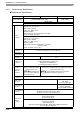
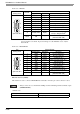
In the case of RS232C
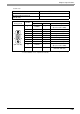
In the case of RS422/RS485
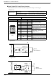
Serial Interface (COM2)
This interface is used to connect an RS422/RS485 serial cable. A D-sub 9-pin socket connector is used.
<GP unit side>
Pin
Arrangement
Pin No.
RS232C
Signal Name Direction Meaning
1 CD Input Carrier Detect
2 RD(RXD) Input Receive Data
3 SD(TXD) Output Send Data
4 ER(DTR) Output Data Terminal Ready
5 SG - Signal Ground
6 DR(DSR) Input Data Set Ready
7 RS(RTS) Output Request to Send
8 CS(CTS) Input Send Possible
9 CI(RI)/VCC Input/-
Called status display
+5V
±5% Output 0.25A
*1
*1 The RI/VCC selection for Pin #9 is switched via software. The VCC output is not
protected against overcurrent. To prevent damage or a unit malfunction, use only the
rated current.
Shell FG -
Frame Ground
(Common with SG)
Pin
Arrangement
Pin No.
RS422/RS485
Signal Name Direction Meaning
1 RDA Input Receive Data A(+)
2 RDB Input Receive Data B(-)
3 SDA Output Send Data A(+)
4 ERA Output Data Terminal Ready A(+)
5 SG - Signal Ground
6 CSB Input Send Possible B(-)
7 SDB Output Send Data B(-)
8 CSA Input Send Possible A(+)
9 ERB Output Data Terminal Ready B(-)
Shell FG -
Frame Ground
(Common with SG)
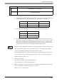
• Always connect close to the GP unit's COM port when terminating with the termination pins
(TRMRX/TRMTX).
GP Connector XM3B-0942-502LX <OMRON Co.>
Interfit Bracket #4-40(UNC)
9
6
5
1
(GP unit side)
9
6
5
1
(GP unit side)