
User guide


GP3000 Series Hardware Manual
6-4
6.2.2 Wiring to the FLEX NETWORK Connector
Remove the wire’s external covering and insert the wire center strand into the opening.
The applicable wire size is AWG28-16. Strip at least 7.0mm [0.28in.] of cover from the wire.
Be sure to remove the FLEX NETWORK Connector from the GP unit prior to starting wir-
ing. Failure to do so may cause an electric shock.
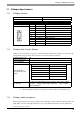
• Tightening torque is 0.25N•m.
• Be sure to tape or put a plastic tube over the shield line.
• Do not solder the wire itself. This could lead to a bad or poor contact.
• Use a small sized screwdriver to tighten the set screws. (Point depth: 0.6mm [0.02in.], point
height: 2.5mm [0.10in.])
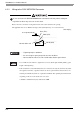
• If the central wire’s end (individual) wires are not twisted correctly, the end wires may either
short against each other, or against an electrode. To use a pin terminal, reference the recom-
mended pin terminal shown below or equivalent terminals. The optimum pin terminal varies
depending on the size of the electric wire to be used.
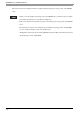
∗-966067-∗ manufactured by Tyco Electronics AMP.
Blue (TR+)
6 to 7 [0.24 to 0.28]
White (TR-)
25 to 35
[0.98 to 1.38]
Shield (SLD)
* Do not solder end
Unit: mm[in.]