
User guide


Chapter 7 CANopen Interface
7-3
7.1 CANopen Specifications
7.1.1 CANopen Interface
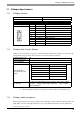
7.1.2 CANopen Data Transfer Settings
CANopen is the networking concept based on the international standard CAN. CANopen is defined as a uni-
form application layer by the DS 301 specifications of the CiA (CAN in automation).
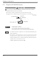
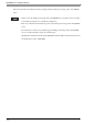
7.1.3 CANopen cable arrangement
The CANopen interface uses D-sub 9-pin plug connector. The plug is assigned with the CAN_H, CAN_L and
CAN_GND connections. CAN_H and CAN_L are two physically different bus levels. CAN_GND is the
common reference potential.
Connector (GP unit side) XM2C-0942-502L <OMRON Co.>
Recommended Cable Connector (Cable side) See page 7-5.
Interfit Bracket #4-40 (UNC)
Pin Arrangement Signal Name Meaning
1
-
2 CAN_L CAN-L bus line
3 CAN_GND CAN ground
4
-
5
-
6
-
7 CAN_H CAN-H bus line
8
-
9
-
Shell FG Frame Ground (Common with SG)
Communication Type
1:N
Connection Method
Bus
Transfer Method
CSMA/NBA. Half-duplex serial transmission.
Transfer distance
speed/Transmission
length
No. of nodes
63 nodes max. Bit variable input: 512 points
*1
, Bit variable output:
512 points
*1
, Integer variable input: 128 points
*2
, Integer variable
output: 128 points
*2
.
*1 When using GP-Pro EX under Ver.2.50, Bit variable enables to input/output 256 points.
*2 When using GP-Pro EX under Ver.2.50, Integer variable enables to input/output 64 points.
1
(GP Unit Side)
6
9
5
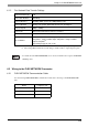
Baud rate
*1
*1 Set the baud rate with the software.
Bus length
1000 kbps 20m
800 kbps 40m
500 kbps 100m
250 kbps (factory settings) 250m
125 kbps 500m
50 kbps 1000m