
User guide


GP3000 Series Hardware Manual
7-4
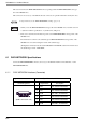
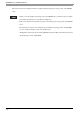
Line termination
To minimize the signal’s reflections from the end of the cable, a line termination shall be placed close to the 2
ends of the bus. Connect both ends of the twisted pair cable (CAN_H and CAN_L) to each LT. Use line
termination whose resistance value is 120 Ω. (Resistance Tolerance: 5% maximum, Rated Power: 1/4 W
minimum).
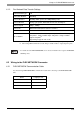
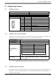
7.1.4 CANopen communication cable and other recommended items
Recommended Cable Connector: CiA-recommended CANopen (CiA DR-303-1) -compatible D-Sub 9-pin
connector (DIN41652).
CANopen Recommended Transfer Cable: CiA-recommended CANopen (CiA DR-303-1) -compatible twisted
pair cables with shield.
• The cable’s resistance value should be 70mΩ/m or less.
• The above diagrams shows the case used the cable connector “XM2D-0901” by OMRON Co.
• Please use your own cables or cable connectors with your guarantee.
LT = Line Termination
Node 1 Node 2 Node n
CAN_H
CAN_L
CAN_GND
Twisted Pair Cable
LT
Diagram 1
Diagram 2
LT
GP
Termination
Resistance
ShieldD-sub 9 pin (socket)
CAN-L
Signal
name
2
CAN-H
CAN-GND
FGShell
3
7
Pin
GP
D-sub 9 pin (socket)
CAN-L
Signal
name
2
CAN-H
CAN-GND
FGShell
3
7
Pin
Shield
Shield
Diagram 1
Diagram 2