
User guide


Chapter 3 Part Names and Functions
3-17
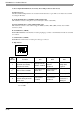
3.6 GP-3700 Series
The following images of an AGP-3750 (AC model) unit.
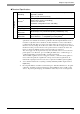
A: Status LED
This LED indicates the GP’s status, e.g. power
input, firmware RUN status or backlight condition.
Also, indicates the status of logic program
execution.
B: Expansion Unit Interface (for internal)
Connects expansion units with communication
features.
C: Ethernet Interface (LAN)
The Ethernet transmission interface (10BASE-T/
100BASE-TX). An RJ-45 type modular jack
connector (8-pole) is used. The LED turns on or off
to indicate the current status.
D: USB Host Interface (USB)
(X
2
)
Complies with USB 1.1. Uses a “ TYPE-A”
connector. Power supply voltage: 5VDC±5%,
Output current: 500mA(max). The maximum
communication distance : 5m.
Color Indicator
Operation
Mode
(Drawing)
Logic execu-
tion mode
(when logic is
enabled)
Green
ON
OFFLINE -
In
operation
RUN
Flashing
In
operation
STOP
Red
ON When power is turned on.
Flashing
In
operation
Major Error
Orange
ON
Backlight burnout or
GP malfunction
*1
*1 Please see "Chapter 9 Replacing the Backlight
(page9-6)" for the details.
Flashing During software startup
LED Indicates
Green ON Data transmission available
Green OFF
No connection or
subsequent transmission
failure
Yellow ON
Data transmission is
occurring.
Yellow OFF No data transmission
Front
A
Left side
B
C
D