
User Manual


Chapter 2 Specifications
2-13
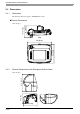
With the GP unit incorporating an emergency switch, the emergency switch activates the contact output, when
the emergency switch is enabled. To reset the emergency stop status (lock status), pull the button forward, or
turn the button in the direction indicated by arrow.
When the emergency switch is pressed, ON/OFF status of the EMG0 to EMG2 signals are as follows:
( ) indicates contact status.
2.3.6 Key Switch Output Interface
• Turning OFF GP unit with the key switch
• Turning ON GP unit with the key switch
Emergency Stop Reset Emergency Stop
EMG0 0 (OFF) 1 (ON)
EMG1 1 (ON) 0 (OFF)
EMG2 1 (ON) 0 (OFF)
• These signal lines must be disconnected (NC) when a GP unit without an emergency switch is
used.
Cable Color/Marking
Color, Number
Signal Name Description
Orange/None KEY_NC
Key Switch b-contact (normally closed)
Rating: DC24V, 300 mA
Orange/Black 1 KEY_NO
Key Switch a-contact (normally open)
Rating: DC24V, 300 mA
• When the key is not turned to ON or OFF, either the “KEY_NO” or the “KEY_NC” signal is
ON. These signals will not simultaneously turn OFF.
• These signal lines must be disconnected (NC) when a GP unit without a key switch is used.
EMG2A
EMG1A
EMG0A
EMG0B
EMG1B
EMG2B
DC24V
GP
OFF
ON
KEY_NO
KEY_NC
GP3000H Cable
DC24V
GP
OFF
ON
KEY_NO
KEY_NC
GP3000H Cable