
Manual


3
About the Relay Output Inductive
Load
Protecting Outputs from Inductive
Load Damage
Depending on the load, a protection circuit
may be needed for the outputs on the
controllers and certain modules. Inductive
loads using DC voltages may create voltage
reflections resulting in overshoot that will
damage or shorten the life of output
devices.
OUTPUT CIRCUIT DAMAGE DUE
TO INDUCTIVE LOADS
• Use an appropriate external protective
circuit or device to reduce the risk of
inductive direct current load damage.
Failure to follow these instructions can
result in injury or equipment damage.
Relay outputs can support up to 240 Vac.
Inductive damage to these types of outputs
can result in welded contacts and loss of
control. Each inductive load must be
equipped with a protection device such as a
peak limiter, RC circuit or flyback diode.
Capacitive loads are not supported by these
relays.
RELAY OUTPUTS WELDED
CLOSED
• Always protect relay outputs from induc-
tive alternating current load damage
using an appropriate external protective
circuit or device.
• Do not connect relay outputs to capaci-
tive loads.
Failure to follow these instructions can
result in death, serious injury, or equipment
damage.
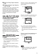
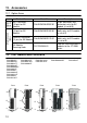
Protective circuit A: this protection circuit
can be used for both AC and DC load
power circuits.
Protective circuit B: this protection circuit
can be used for DC load power circuits.
Use a diode with the following ratings:
• Reverse withstand voltage: power volt-
age of the load circuit x 10.
• Forward current: more than the load cur-
rent.
Protective circuit C: this protection circuit
can be used for both AC and DC load
power circuits.
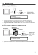
• The above schematics show sinking DC
outputs, but would apply equally to
source outputs.
C
R
~
Output Q
COM
or
+
-
Inductive load
Inductive load
Output Q
COM
+
-
Inductive load
Output Q
COM
+
-
~
or
Varistor