
Manual


31
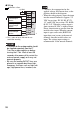
Wiring
indicates a fuse.
• The power for the analog module should be supplied separately from the LT. Turn
the analog module on before turning the LT on. Wait at least 30 seconds after
power-off to restart the external power-supply or it may not operate properly.
• Connect an appropriate fuse for the applied voltage and current draw, at the position
shown in the diagram.
• Do not connect any wiring to unused channels.
15.9 1-ch analog-output module
The detail of the external power supply is: the rated supply voltage is 24 VDC, the rated
input voltage ranges from DC20.4 to 28.8 V. The consumption current is 40 mA (24 VDC)
when the input is not-open, output 100%.
EXM-AMO1HT
Analog Output Specifications Voltage Output Current Output
Rated Output Voltage Range From DC0 to 10 V From DC4 to 20 mA
Load Load Impedance
2 k
Ω
min.*
1
, 1 k
Ω
min.*
2
300 Ω max.
Application Load Type Resistive load
D-A
Conversion
Conversion Time
50 ms*
1
10 ms*
2
Total Output System
Transfer Time
50 ms + 1 scan time*
1
10 ms + 1 scan time*
2
A
B'
B
A'
A
B
PT
2 wires
–
+
24 V
24 V
FG (Functional
Ground) screw
A
B'
B
PT
3 wires
A
B'
B
A
B'
B
A
B'
B
PT
PT
PT
4 wires
A’ A’
A
B
A
B
A
B
PT
PT
PT
2 wires
2 wires
3 wires
4 wires
2 wires
<EXM-ARI8LT>
A
B’
B
A
B’
B
NC
A
B’
B
A
B’
B
A
B’
B
A
B’
B
NC
A
B’
B
A
B’
B
IN 0
IN
IN 2
IN 3
IN 4
IN 5
IN 6
IN 7
+
0V