
Instruction Manual


4
CANopen cable arrangement
The CANopen interface uses DSUB 9-pin plug connector. The plug is assigned with the
CAN_H, CAN_L and CAN_GND connections. CAN_H and CAN_L are two physically
different bus levels. CAN_GND is the common reference potential.
• The cable’s resistance value should be 70mΩ./m or less.
• The above diagrams shows the case used the cable connector “XM2D-0901“ by OMRON Co.
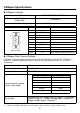
Line termination
To minimize the signal’s reflections from the end of the cable, a line termination shall be placed
close to the 2 ends of the bus. Connect both ends of the twisted pair cable(CAN_H and CAN_L)
to each LT. Use line termination whose resistance value is 120 Ω. (5%, 1/4 W maximum)
LT = Line Termination
Node 1
Node 2
Node n
LT
CAN_H
CAN_L
CAN_GND
Twisted Pair Cable
LT
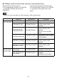
Diagram 1
Diagram 2
GP
Termination
Resistance
ShieldD-sub 9 pin (socket)
CAN-L
Signal
name
2
CAN-H
CAN-GND
FGShell
3
7
Pin
GP
D-sub 9 pin (socket)
CAN-L
Signal
name
2
CAN-H
CAN-GND
FGShell
3
7
Pin
Shield
Shield
Diagram 1
Diagram 2