
Owner's manual


1
GP3000 Series
FLEX NETWORK Interface
Installation Guide
Package Contents
(1) Installation Guide (1) <This Guide>
(2) FLEX NETWORK
Connector (1)
This unit has been carefully packed, with
special attention to quality. However, should
you find anything damaged or missing, please
contact your local GP distributor immediately.
About the Manual
For the detailed information on GP3000
series, refer to the following manual.
• GP3000 Series Hardware Manual
• Maintenance/Troubleshooting Guide
The manuals can be selected from the help
menu of GP-Pro EX or downloaded from
Pro-face Home Page.
URL
http://www.pro-face.com/
Part Names and Functions
Caution
Be sure to read the “Warning/Caution
Information” on the attached sheet before
using the product.
CAUTION
This manual describes the part names and
general specifications related to the FLEX
NETWORK I/F included with the FLEX
NETWORK board type unit of the GP3000
series, as well as the wiring to the FLEX
NETWORK connector. Before using the
FLEX NETWORK connector, be sure to
read this Installation Guide in conjunction
with the attached GP3000 Series’ Installa-
tion Guide.
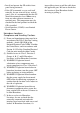
Name Description
AStatus LED
(The logic program is disabled in the AGP-3302B/3301L/3301S. The
Status LED turns on only in Operation Mode (Drawing).)
Left Side
(The figure shows
AGP-3300T unit)A
Front
B
C
Color Indicator
Operation Mode
(Drawing)
Logic execution
mode (when logic is
enabled)
Green
ON
OFFLINE
-
In operation
RUN
Flashing In operation
STOP
Red
ON When power is turned on.
Flashing In operation
Major Error
Orange
ON Backlight burnout
Flashing During software startup