
User guide

4
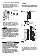
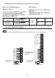
2. 35 mm [1.38 in.] DIN rail mounting
(1) Put the upper groove of the unit on the
upper edge of the DIN rail. Push the
lower side of the unit to the lower edge of
the DIN rail unit it clicks.
(2) While pushing down the hook in the
direction of the arrow with a flat-blade
driver, pull the lower side of the unit and
remove the unit from the DIN rail.
• Check the vertical direction of the unit.
Attach the unit on to the vertical plane
properly. Improper mounting of the unit
may prevent heat release and proper
operation of the unit.
• The unit release hooks are kept open
when not used. Make sure that the unit
release hooks close properly and the
unit is firmly fixed on the DIN rail.
Wiring
• To avoid an electric shock, prior to con-
necting the HTB’s power cord termi-
nals to the power terminal block,
confirm that the HTB’s power supply is
completely turned OFF, via a breaker,
or similar unit.
y Any other power level can damage
both the HTB and the power supply.
y When the FG terminal is connected, be
sure the wire is grounded.
• Make sure to remove the connectors
from the HTB first, then connect cables
to the terminal. Failure to do so may
cause an electric shock.
• Be careful when you remove the con-
nectors that are firmly fit.
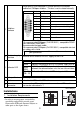
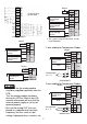
indicates a fuse. indicates load.
15 mm [0.59 in.]
Push down.
1
2
With a flat-blade driver
L
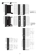
ADDRESS
ONESTENS
BAUD RATE
0
1
2
3
4
5
6
7
8
9
12
10
0
2
4
6
8
0
2
4
6
8
NOT
USED
NOT
USED
NOT
USED
24 V 0 V
– 15 %
+ 9 %
24 V
0I0
I1
I2
I3
I4
I5
I6
I7
I8
I9
I10
I11
Q0
Q1
Q2
Q3
Q4
Q5
Q6
Q7
1
2
3
4
5
6
7
8
9
10
11
COM
COM
(+)
0
1
NC
NC
NC
– V
3
2
4
5
6
7
COM3
COM2
COM1
L
L
L
L
L
L
L
L
48…240 V
48…240 V
48…240 V
24 V
Source Output
Relay Output
Relay Output
Relay Output
(1) Sink Input
24 V
(2) Source Input
(1)
(2)
(1)
(1)
(1)
(2)
(2)
(2)
-15%
+20%
-15%
+10%
30 V
30 V
30 V
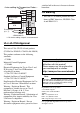
l ≤ 80 mm (3.15 in.)
Ø1...1.5mm
2
AWG 18...16
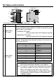
• Please install an applicable fuse to prevent
an overload in the circuit, if necessary.
• The terminals, such as COM, and COM1
to 3, are not connected together internally.
• The input/output connector is
CA7-HTBCNSET-01 made by Pro-face.
13-pin connector for input and 16-pin con-
nector for output, both connectors are
packed.