PL3000 Series Reference Manual
NOTES (1) The copyrights to all programs and manuals included in the “PL3000” (hereinafter referred to as “PL”) are reserved by the Digital Electronics Corporation. Digital grants the use of PL to its users as described in the “Software Operating License Conditions” documentation. Any actions violating the above-mentioned conditions are prohibited by both Japanese and foreign regulations. (2) The contents of this manual have been thoroughly inspected.
Information Symbols This manual uses the following icons: Indicates a warning or a product limitation. Be sure to follow the instructions given with this icon to ensure the safe operation of the PL. Contains additional or useful information. (1) (2) Indicates steps used to accomplish a given task. Be sure to follow these steps in the order they are written. * Indicates useful or important supplemental information. SEE ) Indicates pages containing related information.
Contents NOTES ...................................................................................................................... 1 Information Symbols ................................................................................................. 2 About Pre-installed OS ............................................................................................. 2 Contents ....................................................................................................................
3.4.2 Setup Procedure .................................................................................................3-16 3.5 Checking the Error Log List .......................................................................... 3-17 3.5.1 Description ..........................................................................................................3-17 3.5.2 Setup Procedure .................................................................................................3-18 3.
Chapter 5 Troubleshooting 5.1 Problems and Countermeasures .................................................................... 5-2 5.2 Recovery Procedure ....................................................................................... 5-7 5.2.1 PL with no Pre-installed OS ..................................................................................5-7 5.2.2 PL with Pre-installed OS (Windows®2000/Windows® XP) ..................................5-7 Appendices 1 I/O Map ..........................
6
Setup operation flow The following shows the flow of the setup operation from the purchase of the PL to the completion of the required setup before use. PL with no pre-installed OS 1 Connect peripheral devices and wiring to the PL unit. Connect a commercially available USB keyboard and, when no CD/DVD drive is pre-installed, a commercially available USB CD-ROM drive to the PL unit.
PL with pre-installed OS 1 Connect peripheral devices and wiring to the PL unit. Connect a USB keyboard (commercially available). SEE PL3000 Series Hardware Manual Installation and Wiring • When connecting a Digital FP as a multi-display to the PL3000 series, refer to the following page. SEE Connecting a Digital FP as a multi-display to the PL3000 series (page 9) 2 Turn the PL’s power ON. SEE 2.
Connecting a Digital FP as a multi-display to the PL3000 series You can use a DVI-D/RGB splitter cable (type: CA7-CBLCVDVI-D/RGB-01) to connect two monitors. By doing so, you can display the same screen or different information on both monitors. For each PL3000 series type, when using a Digital DP display as a multi-display, the connection procedure depends on the type of monitor.
(4) In the Intel(R) Graphics Media Accelerator Drive for Mobile tab, click [Graphics Properties]. (5) In the properties window that appears, select the menu to display using [Multi-display]*. Select the main monitor for the primary device and the extended monitor for the secondary device. * For details about each menu, refer to “ Multi-display function types (page 11)”. (6) 10 [Notebook] Select this option when using the PL3000 Series TFT type.
Multi-display function types Twin This allows the same information to be displayed on two monitors. Intel® Dual Display Clone • Like the Twin type, this allows the same information to be displayed on two monitors, however, display may differ according to the selected resolution. Primary Device Secondary Device • When using the TFT type or keypad type of the PL3000 series, if you use the Digital FP as a dual clone monitor, use an RGB cable to connect the PL unit and the monitor.
Extended desktop You can divide one desktop to be displayed on two monitors. Primary Device Secondary Device • When using the TFT type or keypad type of the PL3000 series, if you use the Digital FP as a monitor for an extended desktop, use an RGB cable to connect the PL unit and the monitor. The TFT type and keypad type of the PL series can output only RGB signals. Touch control on the screen cannot be performed while using the extended desktop function.
1 Setting Up Software 1. Software Configuration 2. Setting Up an HDD with no Pre-installed OS 3. Setting Up an HDD with Pre-installed OS 4. PL Dedicated Software This chapter describes the setting procedures for the PL dedicated programs and the setting parameters.
PL3000 Series Reference Manual 1.1 Software Configuration If you purchased a PL unit with the OS pre-installed, the software has been pre-installed. If you purchased a PL unit without the OS pre-installed, you can download each software program from the Pro-face support site “Otasuke Pro!”. SEE 1.2.2 Setting Up the PL Dedicated Software (page1-3) 1.2 Setting Up an HDD with no Pre-installed OS First, when you use a PL with no pre-installed OS, you will need to install either Windows® 2000 or Windows® XP.
Chapter 1 Setting Up Software 1.2.2 Setting Up the PL Dedicated Software Download the necessary drivers and utility software from the Pro-face support site “Otasuke Pro!”. URL http://www.pro-face.com/otasuke/ • Do not install the battery driver when a battery unit is not mounted; otherwise, the Battery Unit Disconnected Error will be displayed. To recover the error, the battery driver should be uninstalled. For procedure to uninstall the battery driver, refer to the following section. 5.
PL3000 Series Reference Manual • When a LAN or a printer is added, you need to change the Windows® system configuration using the following procedure. (1)When the Windows® system configuration settings are changed, the following message appears. When your media is DVD-ROM, replace “CD-ROM” with “DVD-ROM”. Insert the CD labeled “Windows® xx*1 Professional CD-ROM” in the CD-ROM drive (D:), and click [OK].
Chapter 1 Setting Up Software 1.3 Setting Up an HDD with Pre-installed OS In the PL with pre-installed OS, the following software has been installed in advance.
PL3000 Series Reference Manual [Proface] Folder Configuration A [Proface] folder is prepared on the C drive. The following diagram describes the configuration of this folder.
Chapter 1 Setting Up Software • The UPDD device driver has a driver to connect to USB devices built in by default setting. UPDD settings are disabled by default setting for the PL3000 series box type. When connecting the unit to the FP Series, these setting should be enabled. (1)Click the icon shown above. (2)Change the Enabled check mark from 8 to 9.
PL3000 Series Reference Manual 1.3.1 Setting Up OS Set up the Pre-installed OS in the PL unit. Windows® 2000 Setup Procedure This section describes the setup procedure for Windows® 2000. The setting parameters vary depending on your environment. Ask your network administrator for the appropriate parameters. • When setup is completed, a README file is created on the desktop. The README file contains details regarding software and information released since the creation of this manual.
Chapter 1 Setting Up Software (3) The [Regional Settings] screen will appear. After entering the data for your area, click the [Next] button. (4) The [Personalize Your Software] screen will appear. After entering your name [Name] and [Organization], click the [Next] button. (5) The [Your Product key] screen will appear. After entering the product key data on the license sticker, click the [Next] button. (6) The [Computer Name and Administrator Password] screen will appear.
PL3000 Series Reference Manual (8) The [Network Settings] screen will appear. Choose whether to use typical or custom settings depending on your PC circumstantce. (9) The [Workgroup or Computer Domain] screen will appear. Choose whether to make your PC on a network or not depending on your PC circumstance. (10) [Performing Final Tasks] is automatically done by the PL. The [Completing the Windows 2000 Setup Wizard] will appear. Press the [Finish] button and the system will automatically restart.
Chapter 1 Setting Up Software Windows® XP Setup Procedure This section describes the setup procedure for Windows® XP. The setting parameters vary depending on your environment. Ask your network administrator for the appropriate parameters. • When setup is completed, a README file is created on the desktop. The README file contains details regarding software and information released since the creation of this manual. Read the README file first after setup is completed.
PL3000 Series Reference Manual (4) The [What’s your computer’s name?] screen will appear. After entering the computer’s name, click [Next] to continue. At default setting, the computer’s name has been entered. If it’s not necessary to change it, click [Skip]. (5) The [What’s your Administrator password?] screen will appear. If the password is set, enter the password in [Administrator password:] and [Confirm password:] and click [Next]. If the password is not set, click [Skip].
Chapter 1 Setting Up Software 1.4 PL Dedicated Software 1.4.1 Driver Six types of dedicated PL drivers (AHCI, Chipset, Audio, Graphic Accelerator, LAN and Touch Panel Driver (Mouse Emulator)) are available. If you purchased the PL with no pre-installed OS, download the drivers from the Pro-face support site “Otasuke Pro!”. (A PL unit that has been recovered using the Recovery Media will have all the required drivers installed).
PL3000 Series Reference Manual LAN Driver This is a driver for the IntelR Ethernet Controller. Installing the Ethernet Controller Driver enables LAN1 and LAN2 to be available. • For instructions on how to start a PL unit over LAN, refer to the following. SEE 3.7 Restarting/Shutting Down the PL from a Remote Server (page3-27) Touch Panel Driver (Mouse Emulator) Install the Touch Panel Driver in the PL unit. It’s necessary to agree to DMC’s Mouse Emulator Software (TSC-1310D/DD) License in advance.
Chapter 1 Setting Up Software 1.4.2 Special Application Program Features The special programs designed for the PL unit are located in the following folders. The file storage locations given in the table below assume that the [Proface] folder already exists on drive C. File Name BlCtrl.exe BlSaver.scr BlBright.cpl Keyclick.exe Ioctl.dll Smonras.dll SmSRvCPL.cpl Sysmon.sys SystemMonitor.
PL3000 Series Reference Manual Backlight Brightness Adjustment: BlBright.cpl Backlight brightness can be set to one of four levels: Level 0, Level 1, Level 2 or Level 3.
Chapter 1 Setting Up Software System Monitor Property: SmSRvCPL.cpl This program allows the user to set the notification method used in event of an error/alert while the RAS feature monitors the system. System File: Sysmon.sys This system file allows use of the RAS and System Monitoring features. This file should not be modified. If it is modified, the RAS and System Monitoring features may not operate correctly. System Monitoring/RAS Application: SystemMonitor.
PL3000 Series Reference Manual 1-18
2 System Setup 1. System Setup Screen Operation 2. System Parameters Setting This chapter describes how to operate the system setup screen and how to set system parameters.
PL3000 Series Reference Manual 2.1 System Setup Screen Operation This section describes the operation of the BIOS setup screen. • Normally, use only the factory (default) settings. (1) Connect a USB keyboard to the PL. (2) Turn the PL’s power ON. (3) After the boot-up screen comes up, press the [F2] key. The setup utility starts and the following screen appears. Menu KEYBOARD ACTION KEYS Help area Provides a summary of the keyboard keys used to carry out the set-up.
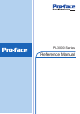
Chapter 2 System Setup BIOS Setup Screen Configuration MAIN )2-4 page Specify the drive/date. Advanced 2-7 page Set the system details. ) IDE Channel/SATA Port 2-5 page Display the information for the connected devices. ) Processor Configuration 2-10 page Set the CPU. ) CPU Thermal Configuration 2-11 page Set the CPU temperature monitoring feature. ) Power-ON Configuration 2-12 page Set the PL operations at power-on. ) Video (Intel IGD) Configuration 2-14 page Set the graphics details.
PL3000 Series Reference Manual 2.2 System Parameters Setting Select the items to set up the system information. Here, we introduce the system parameters of each item. • Normally, use only the factory (default) settings. • An item in [ ] indicates the factory default setting. 2.2.1 Main System Time Shows the time which the PL currently recognizes.
Chapter 2 System Setup System Memory Shows the capacity of the “System Memory”. Extended Memory Shows the capacity of the “Extended Memory”. It is the loaded memory - the size of the Video Memory. IDE Channel / SATA Port Point out the cursor at the [IDE Channel 0 Master], [IDE Channel 0 Slave], [IDE Channel 1 Master], [IDE Channel 1 Slave], [SATA Port 0], [SATA Port 1] on the “Main screen”, and then press the [Enter] key, so that the following screen is shown.
PL3000 Series Reference Manual Multi Sector Transfers Specifies the number of sectors per block, which are transferred to the memory. When [Type] is [None] or [Auto], the selection is disabled. [Disabled] Transfers by sector. [2 Sectors] Transfers 2 sectors at a time. [4 Sectors] Transfers 4 sectors at a time. [8 Sectors] Transfers 8 sectors at a time. [16 Sectors] Transfers 16 sectors at a time.
Chapter 2 System Setup 2.2.2 Advanced Processor Configuration Point the cursor to [Advanced Processor Configuration] and press the [Enter] Key to go to the CPU set-up screen. SEE Processor Configuration (page2-10) Power-ON Configuration Point the cursor to [Power-ON Configuration] and press the [Enter] Key to go to the set-up screen for the PL operations at power-on.
PL3000 Series Reference Manual DMI Event Logging Point the cursor to [DMI Event Logging] and press the [Enter] Key to go to the DMI event logging set-up screen. SEE DMI Event Logging (page2-25) Soft Mirror Status Point the cursor to [Soft Mirror Status] and press the [Enter] Key to go to the display screen for the soft mirror status. SEE Soft Mirror Status (page2-26) Installed O/S Specifies a type of OS of the unit. [Other] Set when using a non-Plug and Play OS.
Chapter 2 System Setup CMOS Time Not Set Summary Screen Specifies whether the configuration information of the running system (Summary Screen) is displayed. [Enabled] Shows the Summary Screen. [Disabled] Does not show the Summary Screen. Enable Memory gap Specifies an enabled/disabled state for the Memory gap. [Enabled] Reserves a memory gap for an expansion card. [Disabled] Use this setting normally.
PL3000 Series Reference Manual Processor Configuration Specifies the settings for the CPU. Point the cursor to [Processor Configuration] on the [Advanced] screen and press the [Enter] Key to display the following screen. CPU Thermal Configuration Point the cursor to [CPU Thermal Configuration] and press the [Enter] Key to go to the set-up screen for CPU temperature monitoring. Core Multi-Processing Specifies whether to distribute processing using multiple processor cores.
Chapter 2 System Setup CPU Thermal Configuration Specifies the settings for the CPU temperature monitoring. Point the cursor to [CPU Thermal Configuration] on the [Advanced Processor Configuration] screen and press the [Enter] Key to display the following screen. Thermal Control Circuit Specifies whether to use the CPU temperature protection feature. [Disabled] The CPU temperature protection feature is not used. [TM1] The CPU is operated at 50% duty ratio.
PL3000 Series Reference Manual Power-ON Configuration Specifies the PL operations at power-on. Point the cursor to [Power-ON Configuration] on the [Advanced] menu and press the [Enter] Key to display the following screen. Power On Delay Specify whether to set standby time before the system starts up. [Enabled] The system waits for 4 seconds before start-up. [Disabled] The system starts up normally.
Chapter 2 System Setup Power On Beep Specify whether to sound a “beep” upon system boot-up. [Enabled] Sounds at start-up. [Disabled] Does not sound at start-up.
PL3000 Series Reference Manual Video (Intel IGD) Configuration Specifies graphic-related settings. Point the cursor to [Video (Intel IGD) Configuration] on the [Advanced] screen and press the [Enter] Key to display the following screen. • When using the PCI graphic board, make sure to set the IGD#0 setting to [Disabled]. • The PCI graphic board can be used only with the PL3000 series box type. IGD #0 Shows an enabled/disabled state for graphics device 0 in the chipset.
Chapter 2 System Setup DVMT 3.0 Mode Specifies the form of the memory used by the graphic in the chipset. When the IGD #0 is [Disabled], this option is not displayed. [Fixed] The fixed area is used as video memory. [DVMT] The DVMT (Dynamic Video Memory Technology) feature is used so that video memory is dynamically allocated from main memory. [Combo] Combination of [Fixed] and [DVMT].
PL3000 Series Reference Manual Cache Memory Configuration Specifies the parameters for the cache memory. Point the cursor to the [Cache Memory] on the [Advanced] screen and press the [Enter] Key, so that the following screen will be displayed. Memory Cache Specifies an enabled/disabled state for the Memory Cache. [Enabled] Uses cache memory. [Disabled] Does not use cache memory. Cache System BIOS area Specifies the cache set-up for the System BIOS area.
Chapter 2 System Setup Cache Base 512-640k Specifies the cache set-up for the Base Memory, 512 ~ 620k. [uncached] Does not cache the System BIOS area. [Write Through] Uses Write Through method. [Write Protect] Write protects the System BIOS area. [Write Back] Uses Write Back method. Cache Extended Memory Area Specifies the cache set-up for the Extended Memory area. [uncached] Does not cache the System BIOS area. [Write Through] Uses Write Through method.
PL3000 Series Reference Manual Integrated Device Configuration Specifies the settings for the integrated devices. Point the cursor to [Integrated Device Configuration] on the [Advanced] screen and press the [Enter] Key to display the following screen. I/O Device Configuration Point the cursor to [I/O Device Configuration] and press the [Enter] Key to go to the set-up screen for the I/O addresses and interrupt Nos. of the integrated devices.
Chapter 2 System Setup AHCI Configuration Specifies whether to use the AHCI mode for SATA. When [SATA Operational Mode] is [Compatible], this option is not displayed. [Enabled] Uses AHCI mode. [Disabled] Does not use AHCI mode. • When installing the OS with [AHCI Configuration] set to [Enable], download Intel Matrix Storage Manager from the Pro-face support site “Otasuke Pro!”. For the detailed installation procedure, refer to the “Otasuke Pro!” site. http://www.pro-face.
PL3000 Series Reference Manual I/O Device Configuration Specifies the address and interrupt level of the I/O ports. Point the cursor to the [I/O Device Configuration] on the [Integrated Device Configration] screen and press the [Enter] Key, so that the following screen will be displayed. COM Port 1, 2, 3, 4 Specifies whether to use the COM port. [Enabled] Uses the COM port. [Disabled] Does not use the COM port. Base I/O Address Specifies the base I/O address of the COM port.
Chapter 2 System Setup PCI Configuration Specifies the PCI IRQ parameters. Point the cursor to the [PCI Configuration] on the [Integrated Device Configration] screen and press the [Enter] Key, so that the following screen will be displayed. PCI/PNP ISA IRQ Resource Exclusion Point the cursor to [PCI/PNP ISA IRQ Resource Exclusion] and press the [Enter] Key to go to the PCI/PNP ISA IRQ screen. PCI IRQ line 1 to PCI IRQ line 8 Specifies the interrupt No. of the PCI. [Disabled] The PCI is not used.
PL3000 Series Reference Manual PCI/PNP ISA IRQ Resource Exclusion Specifies the IRQ resource to be reserved for the ISA interrupt. Point the cursor to [PCI/PNP ISA IRQ Resource Exclusion] on the [PCI Configuration] screen and press the [Enter] Key to display the following screen. IRQ3, 4, 5, 7, 10, 11, 15 2-22 [Available] IRQ is not reserved. [Reserve] IRQ is reserved.
Chapter 2 System Setup USB Controller Configuration Specifies the USB controller options. Point the cursor to [USB Controller Configuration] on the [Integrated Device Configuration] screen and press the [Enter] Key to display the following screen. USB Controller #0 Displays the enabled/disabled status of the USB controller #0. [Enabled] USB controller #0 is enabled. [Disabled] USB controller #0 is disabled. USB Controller #1 Specifies whether to use the USB controller 1.
PL3000 Series Reference Manual USB Controller #3 Specifies whether to use the USB controller 3. When [USB Controller #0], [USB Controller #1] or [USB Controller #2] is [Disabled], this option is fixed to [Disabled] and not displayed. [Enabled] Uses the USB controller #3. [Disabled] Does not use the USB controller #3. USB 2.0 Controller Specifies whether to use the USB 2.0 controller. When [USB Controller #0] is [Disabled], this option is fixed to [Disabled] and not displayed. [Enabled] Uses the USB 2.
Chapter 2 System Setup DMI Event Logging Specifies the parameters related to DMI event logging. Point the cursor to the [DMI Event Logging] on the [Advanced] screen and press the [Enter] Key, so that the following screen will be displayed. Event log validity Shows the status of the event log storage area. [Valid] The status is normal. [Not valid] The status is abnormal. Event log capacity Shows the status of the area to which event logs are written. [Full] The area is full.
PL3000 Series Reference Manual Clear all DMI event logs Specifies whether all the recorded DMI event logs need to be deleted. [No] Does not delete event logs. [Yes] Deletes event logs. Automatically reset to [No] after the data is initialized. Soft Mirror Status Displays and specifies the soft mirror status. Point the cursor to the [Soft Mirror Status] on the [Advanced] screen and press the [Enter] Key to display the following screen. Mirror System Displays the soft mirror status.
Chapter 2 System Setup 2.2.3 Security Set User Password / Set Supervisor Password Allows a password to be set with a maximum of 8 characters. When any password is not needed, do not input any values in the [Enter New Password] and press just the [Enter] key. Password on boot Specifies whether a password should be needed at the Start-Up. When no password has been set for [Set User Password] or [Set Supervisor Password], the selection is disabled. [Enabled] Requests password.
PL3000 Series Reference Manual 2.2.4 Boot Specifies an order for boot-up devices. The boot-up devices are specified in the Boot priority order list and are searched for from the top of the list in sequence. By using the [+] or [-] keys, change its order. To change the device to be booted up, use the [x] key to move the device from the Boot priority order list to the Excluded from boot order list and vice versa.
Chapter 2 System Setup 2.2.5 Exit Exit Saving Changes Point the cursor to the [Exit Saving Changes] on the [Exit] menu and press the [Enter] Key, the current configuration is saved and the setting procedure is ended. • Pressing the [F10] key performs the same operation. Exit Discarding Changes Point the cursor to the [Exit Discarding Changes] on the [Exit] menu and press the [Enter] Key, the current configuration is NOT saved but the setting procedure is ended.
PL3000 Series Reference Manual 2-30
3 PL Monitoring Features 1. RAS Features 2. Setting Menus 3. Monitoring the PL Status 4. Checking the Status of the PL Being Monitored 5. Checking the Error Log List 6. Monitoring Errors/Alerts from a Remote Server 7. Restarting/Shutting Down the PL from a Remote Server 8. Setup Guide for the system monitor property 9. Setup Guide for the System Monitor Screen 10.Displayed Messages 11.Restrictions This chapter describes various ways to monitor the status of the PL.
PL3000 Series Reference Manual 3.1 RAS Features 3.1.1 RAS Features Errors/Alerts which can be Detected by RAS Features RAS, which stands for Reliability, Availability, and Serviceability, is a device-level monitoring function that provides a variety of features to improve the reliability of your PL system. Though the standard set of RAS features used will vary depending on the devices used, the following features are used to provide Error/Alert Monitoring and External Input Signal support.
Chapter 3 PL Monitoring Features • An administrator Authentication is required for executing SMART Monitoring. • PL units do not support monitoring of CF card life. • To enable the remote reset feature’s input, specify [Disabled] for the RAS Reset Port Mask feature of the BIOS. SEE 2.2.
PL3000 Series Reference Manual Error/Alert Notification Also, when either the one of the above mentioned error/alert occurs, or an external signal input is received, the following types of alarm processing output signals and features are supported by the PL. • External Output Signal General-Purpose Output (DOUT 2-bit) SEE • LED Indicator (2 colors, 1 lamp) The three-color LED on the front face is used to indicate the PL system conditions. It is also used as a power ON/OFF indicator.
Chapter 3 PL Monitoring Features RAS Feature Overview System Monitor *1 System Properties Backlight, Voltage, Fan RPM, Temperature Alarm Detection Level Settings Enable/Disable Settings SMART Alarm, Power Alarm, Fan Alarm, Internal Temperature Alarm, Output Settings, Watchdog Timer Value Settings, Watchdog Reset Enable/Disable Settings Mirroring Disk Status Monitoring Battery Status Monitoring *2 *2 Popup Message OS Hibernation OS Shutdown User Application System Monitoring Application WDT Reset
PL3000 Series Reference Manual LED Indicator LED Color System Status output condition Green (Lit) Normal Operation (Power is ON) None Green (Blinking) System is NOT running (Soft OFF) None Orange (Lit) A RAS error/alert occurred. LED is enabled via System Monitor Property. Orange/Red (Blinking) Backlight burnout is detected. None Not Lit Power is OFF - External Input Signals The PL’s RAS interface connector uses the following input signals.
Chapter 3 PL Monitoring Features (Interface Circuit) +5V 1.8kΩ 1/10W R 1.8kΩ 1/10W DIN0(+) DIN1(+) No polarity - for Sink / Source input pin # 4 pin # 5 R Cable DC12V to 24V DINCOM pin # 9 switch or other switching device PC357 • General-Purpose Input (DIN) level must be 1.5 seconds or longer to be detected. It may not detect under 1.5 seconds. • Be sure the voltage value between terminals is controlled via the input voltage, so that the PL is operated within its recommended range.
PL3000 Series Reference Manual The System Monitor property can be used to enable or disable any of these output signals. Rated Voltage DC12V to 24V Maximum Load Current 120mA/point Out Voltage Drop 1.5V or less (at 100mA load current) Output Points 2 points Isolation Method Photocoupler Isolation Dielectric Strength Voltage 500V or more External Power Supply DC12V / 100mA ( Interface Circuit ) +5V R DOUT0(+) pin # 2 DOUT1(+) pin # 3 Load *1 Cable SSTA06 DC12V to 24V PC357 4.
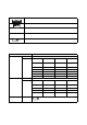
Chapter 3 PL Monitoring Features 3.2 Setting Menus Monitoring the PL Status Beep Error! E.g. Temperature error occurs. ) Description (page3-11) ) Setup Procedure (page3-11) The occurrence of the error is displayed. Checking the Status of the PL Being Monitored System Monitor +5.
PL3000 Series Reference Manual Monitoring Errors from a Remote Server Error/alert is checked. Error/alert occurs. ) Description (page3-20) ) System Configuration (page3-21) ) Monitoring using Pro-Server with Pro-Studio or Pro-Server EX (page3-25) The error can be checked even from a remote office.
Chapter 3 PL Monitoring Features 3.3 Monitoring the PL Status 3.3.1 Description Beep Error! Error/alert occurs. The occurrence of the error/alert is displayed. Before starting the setup procedure, specify the items you want to monitor with the RAS features. When an error/alert occurs, notification is provided according to the specified method. 3.3.2 Setup Procedure This section describes the procedures to set the PL to monitor specific items using the RAS features.
PL3000 Series Reference Manual (3) Check [Enable]. (4) For [Error Action], check [Buzzer] and [PopupMessage]. Enter the character string you want to display as a pop-up message into the entry field. (Example: Temperature Error) • For the details of the Buzzer and PopupMessage features, refer to the following section.. SEE Error/Alert Notification (page3-4) (5) Click [Apply]. (6) Click [OK] to complete the setting. When the monitoring starts, the System Monitor icon appears in the task tray.
Chapter 3 PL Monitoring Features • System Monitor also operates as Windows’s Services. When System Monitor applications do not start, the System Monitor Service execute the RAS events setup in the System Monitor Property. You can check the System Monitor Service’s operation state by selecting [Control Panel] -> [Administrative Tools] -> [Services]. • The pop-up message displayed when the System Monitor Service detects an error/alert differs from ordinary ones.
PL3000 Series Reference Manual 3.3.3 When an Error Occurs (1) A buzzer sounds and a pop-up message is displayed. • The Error Action is performed only one time when an error is detected for each monitoring item. • To stop the buzzer, click the [Buzzer Off] button in the pop-up message dialog box. If the pop-up message is hidden, click the [Buzzer Off] button displayed in the System Monitor screen. • You can also display the [System Monitor] screen by pressing [Show Window] on the pop-up message window.
Chapter 3 PL Monitoring Features 3.3.4 When an Alert Occurs (1) A buzzer sounds and a pop-up message is displayed. • The Alert Action is performed only one time when an alert is detected for each monitoring item. • To stop the buzzer, click the [Buzzer Off] button in the pop-up message dialog box. If the pop-up message is hidden, click the [Buzzer Off] button displayed in the [System Monitor] screen.
PL3000 Series Reference Manual 3.4 Checking the Status of the PL Being Monitored 3.4.1 Description System Monitor +5.0V Pass +12V Pass VcoreA Pass Check the status of the PL being monitored with the RAS features from the System Monitor screen. You can also use this screen to check error/alert details. 3.4.2 Setup Procedure • For details about the setup procedure, refer to the Setup Guide. SEE (1) 3.
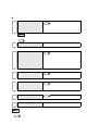
Chapter 3 PL Monitoring Features 3.5 Checking the Error Log List 3.5.1 Description Error 2007/6/19 10:04:12 Error 2007/6/19 12:15:24 Error 2007/6/19 15:36:08 Check the location and action of the previous error/alert on the Event Viewer screen.
PL3000 Series Reference Manual 3.5.2 Setup Procedure (1) Select [Control Panel] - [Administrative Tools] - [Event Viewer] to display the Event Viewer screen. Select [System] to display the system log list. • The Hardware Reset from a Watchdog Timer Error and the reset input for the RAS port cannot be logged. (2) Error logs can be recognized by [System Monitor] displayed in the Source column. Select the row of the error log you want to check and double-click it.
Chapter 3 PL Monitoring Features (3) The [Event Properties] screen appears. The error message is displayed in the [Description] area.
PL3000 Series Reference Manual 3.6 Monitoring Errors/Alerts from a Remote Server 3.6.1 Description Error/alert occurs. Error/alert is checked. Monitor and control the System Monitor/RAS features remotely via the host PC in which Pro-face’s ProServer with Pro-Studio (optional) or Pro-Server EX (optional) is installed. To use this feature, you need Pro-Server with Pro-Studio Ver. 3.12 or higher, or, Pro-Server EX Ver.1.20 or higher. Please also refer to the manuals of the Pro-Server. SEE 3-20 3.6.
Chapter 3 PL Monitoring Features 3.6.2 System Configuration The system employing this feature is configured as illustrated below. Server PC User Application Two-way feature Pro-Server with Pro-Studio Ver. 3.12 or higher, or Pro-Server EX Ver. 1.20 or higher Remote RAS Server Program (IPC_RAS.npj) Ethernet Client PL [System Monitor/RAS Feature] • SystemMonitor.exe • System Monitor Property • Ioctl.dll • Smonras.dll • Sysmon.
PL3000 Series Reference Manual The status of the System Monitor/RAS feature is transferred to the Pro-Server via Ethernet from the SystemMonitor.exe. This allows users to monitor errors/alerts by monitoring the device address assigned by Pro-Studio in which the shared memory has been stored. User Application Server PC Pro-Server with Pro-Studio Ver. 3.12 or higher (Optional), or Pro-Server EX Ver.1.20 or higher Two-Way feature Pro-Easy.dll Ethernet User Application SystemMonitor.
Chapter 3 PL Monitoring Features List of Device Addresses Device Type Device Device Symbol VcoreA *1 VcoreB *1 +3.3V *1 +5.0V *1 +12V *1 +1.
PL3000 Series Reference Manual Value to be Written Decimal Number Hexadecimal Number 1 0001 2 0002 257 0101 258 0102 Operation Shutdown Reboot Forced Shutdown Forced Reboot Bit Assign of Error Event, and Error Mask Device Name DIN Error Event Error Mask 3-24 Item DIN0 DIN1 VcoreA Voltage Error VcoreB Voltage Error +3.3V Voltage Error +5.0V Voltage Error +12V Voltage Error +1.
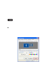
Chapter 3 PL Monitoring Features 3.6.3 Monitoring using Pro-Server with Pro-Studio or Pro-Server EX Setting Up the Client PL (1) Double-click [System Monitor Property] in [Control Panel] to display the [System Monitor Property] screen. (2) On the [Remote RAS] tab, put a check mark in the [Enable] checkbox. • For details about the setup procedure, refer to the Setup Guide. SEE 3.8.
PL3000 Series Reference Manual Setting Up the Server PC (1) On the server PC, download the software from the Pro-face support site “Otasuke Pro!”. Follow the attached instructions to copy the downloaded file to the designated file. (2) Start up the Pro-Studio. (3) Register the PL you want to include in the network to the network station, and edit the participant stations.
Chapter 3 PL Monitoring Features 3.7 Restarting/Shutting Down the PL from a Remote Server 3.7.1 Description Via the network Server on which Pro-Server is not installed Restart Exit Restart or shut down the PL unit from a server on which Pro-Server is not installed. It is assumed that the [Proface] folder has already been created on the unit at this location. • For the operation procedure of this feature, refer to the online help of the Remote Shutdown Application.
PL3000 Series Reference Manual Starting/Shutting Down the PL from the Standby or Sleep Mode To start/shut down the PL from the standby or sleep mode, configuration of the [System] setting in the [Control Panel] is required. • To start/shut down the PL from the shut-down mode, it is not necessary to configure the [System] setting in the [Control Panel]. (1) Start [Control Panel] from the Start menu. (2) Start the [System]. (With Windows® XP, it is in the [Performance and Maintenance] category.
Chapter 3 PL Monitoring Features 3.8 Setup Guide for the system monitor property The System Monitor Property allows you to specify PL items you want to monitor with the RAS features and the notification method used when errors/alerts occur. When an error/alert occurs, notification is provided according to the method specified in the System Monitor Property. • For procedure to set up the System Monitor Property, refer to the following section. 3.3.
PL3000 Series Reference Manual The following shows the default settings of each feature.
Chapter 3 PL Monitoring Features 3.8.1 Voltage / Fan / Temperature / Backlight / DIN0 / DIN1 • The Voltage, Fan, Temperature, Backlight and DIN1 tabs display the same setting items as the DIN0 tab. • DIN1 tab cannot be set up when a checkmark is off in the [Enable] checkbox of Remote reset tab. Remote reset feature, refer to the following section. 3.8.5 Remote reset (page3-35) SEE Item Operation Enable When this option is checked, monitoring of the item starts.
PL3000 Series Reference Manual 3.8.2 SMART Item Operation Enable When this option is checked, monitoring of SMART starts. Alert Action Specifies the action(s) taken when the System Monitor detects that the allowable range is exceeded. You need to check [Enable] before you can select actions. DOUT0 to 1 Output from the RAS port. LED The front LED lights orange. Buzzer Sounds a buzzer as an alarm.
Chapter 3 PL Monitoring Features 3.8.3 Remote RAS Item Enable Throw device Operation When this option is checked, the remote RAS feature starts. Specifies the item(s) to be monitored. Specifies the IP address used for the connection with the Pro-Server. Interface Server Filter • When 2 or more IP Addresses are allocated to the PL unit, the [Auto] cannot be selected. Enter settings that allow the reading of a fixed IP Address from a DHCP server.
PL3000 Series Reference Manual 3.8.4 Watchdog Timer Item Operation Enable When this option is checked, the Watchdog Timer is enabled. Timeout(sec.); Specifies the timer duration. Error Action Specifies the action(s) taken when the System Monitor detects that the allowable range is exceeded. Popup Message When [PopupMessage] is specified as an action, the characters entered in the field (e.g. Watchdog Timer Error) are displayed as a popup message.
Chapter 3 PL Monitoring Features 3.8.5 Remote reset Item Enable Operation When this option is checked, the Remote Reset is enabled.
PL3000 Series Reference Manual 3.8.6 Battery Item Operation Enable When this option is checked, the Battery Monitoring is enabled. Error Action Specifies the action(s) taken when the System Monitor detects that the allowable range is exceeded. PopupMessage When [PopupMessage] is specified as an action, the characters entered in the field (e.g. Battery Unit %s Error) are displayed as a popup message. For the details about the PopupMessage feature, refer to the following section.
Chapter 3 PL Monitoring Features • The [Battery] tab is displayed only when a battery is mounted, allowing you to specify the Battery feature. • Battery units cannot be used with pre-installed OS type PL units that have SSD (solid-state drive) units. • When power failure is recovered within the delay time specified with the [Delay time for execution] option, the battery returns to normal operation. For the procedure to recover from a power failure, refer to the following section. SEE 3.3.
PL3000 Series Reference Manual 3.9 Setup Guide for the System Monitor Screen You can check the status of the PL being monitored. Click the tab of the item you want to check. • PL items you want to monitor with the RAS features and the notification method used when errors/alerts occur are set from the System Monitor Property. For the System Monitor Property settings, refer to the following. SEE 3-38 3.
Chapter 3 PL Monitoring Features 3.9.1 Voltage / Fan / Temperature / Backlight / Watchdog Timer / Soft Mirror • The Temperature, FAN, and Soft Mirror tabs display the same items as the Voltage tab. • The Backlight and Watchdog Timer tabs display [Status] only. Item Operation Name Displays the monitoring item. Status Specifies the item to be monitored. The status of each monitoring item is displayed.
PL3000 Series Reference Manual 3.9.2 SMART Item Device No. Operation Displays the number assigned to the hard disk/SSD/CF card to be monitored. Displays the model of the hard disk/SSD/CF card. Model Status • SMART monitoring can be executed only on drive that have been subjected to an operational inspection by Digital Electronics Corporation. The background of drives that have not been given an operational inspection is gray. Specifies the item to be monitored.
Chapter 3 PL Monitoring Features Item Operation Selecting [SSD/CF Status] displays the [SSD/CF Status] dialog box, which allows confirmation of remaining product life. Remaining product life is calculated according to the number of write operations made to the SSD, and is displayed as a percentage value with one decimal place. SSD/CF Status • Monitoring of SSD life is only possible on pre-installed OS type PL units that have SSD units. PL units do not support monitoring of CF card life.
PL3000 Series Reference Manual 3.9.3 Battery Item Operation Name Displays the monitoring item. Status Specifies the item to be monitored. The status of each monitoring item is displayed. [Pass]: Normal [Disable]: Not monitored [Error]: Power failure occurred Value Displays the power supply method. [AC Power]: AC-powered [Battery]: Battery-powered Buzzer Off When [Buzzer] is selected for the error notification method, you can stop the buzzer by clicking [Buzzer Off].
Chapter 3 PL Monitoring Features • Do not install the battery driver when a battery unit is not mounted; otherwise, the Battery Unit Disconnected Error will be displayed. To recover the error, the battery driver should be uninstalled. For procedure to uninstall the battery driver, refer to the following section. SEE 5.1 Problems and Countermeasures (page5-2) • Remaining level of battery power supply cannot be monitored. • The battery unit and driver communicate via COM2 port.
PL3000 Series Reference Manual 3.10 Displayed Messages Error/Alert Pop-up Messages When an error/alert occurs while the “Popup Message” option is enabled for Error Action/Alert Action, the following messages appear on the pop-up message output screen under the factory settings. Error/Alert Type VcoreA VcoreB +3.3V +5.0V +12.0V Message VcoreA Power Supply Error VcoreB Power Supply Error +3.3V Power Supply Error +5.0V Power Supply Error +12V Power Supply Error -12.0V -12V Power Supply Error +1.8V +1.
Chapter 3 PL Monitoring Features Messages Displayed on the Event Viewer Screen The error types/locations shown by the Event Viewer are as follows. Error/Alert Type Message VcoreA VcoreA voltage Error has occurred. VcoreB VcoreB voltage Error has occurred. +3.3V +3.3V Error has occurred. +5.0V +5.0V Error has occurred. +12.0V +12V Error has occurred. -12.0V -12V Error has occurred. +1.8V +1.8V Error has occurred. CPU FAN CPU Fan Error has occurred.
PL3000 Series Reference Manual Error/Alert Action • The data shown in the table's “” indicate the error/alert type/location. • The actions to be taken after an error/alert occurs are set via the System Monitor Property. Error/Alert Action 3-46 Message Buzzer Buzzer has sounded because of error. Buzzer has sounded because of alert. Popup Message Popup Message has been shown because of error. Popup Message has been shown because of alert.
Chapter 3 PL Monitoring Features Error Messages Displayed during Device Reading/Writing Error Code Error Message Decimal Number Hexadecimal Number 9530 253Ah RAS Initialization Error 9531 253Bh Command not supported. 9532 253Ch Access type not supported. 9533 253Dh Read/Write type not supported. 9534 253Eh Access to the device is rejected. 9535 253Fh Value setting to the device/retrieval failed.
PL3000 Series Reference Manual 3.11 Restrictions Supported Pro-Server Features The following table lists the features of the Pro-Server that are supported by the PL. For the details of each feature, refer to “Pro-Server with Pro-Studio for Windows Operation Manual”. Pro-Server Feature O: Supported X: Not Supported DDE Feature O Simplified DLL Feature (ProEasy.
4 Using Key Commands to Input Text and Operate Applications 1. About KeyPad Module 2. Features of KPM 3. Using KPM to Operate Applications from Shortcuts 4. Configuring the Keyboard Layout 5. Restrictions This chapter describes the features of KeyPad Module, which is included with the PL-3∗00K Series.
PL3000 Series Reference Manual 4.1 About KeyPad Module KeyPad Module (hereafter referred to as “KPM”) is a keyboard module that is included with the PL-3∗00K Series. You can operate the panels using the keypad and mouse pointer in the front panel of KPM. In addition to the panel operation, the KPM also allows you to input text and activate shortcut operations of user applications running on the PL (by assigning a key code to each application).
Chapter 4 Using Key Commands to Input Text and Operate Applications • For details about each component of KPM and its function, refer to the following section. SEE PL3000 Series Hardware Manual “Part Names and Functions” • For operating applications from shortcuts on KPM, refer to the following section. SEE 4.3 Using KPM to Operate Applications from Shortcuts (page 4-6) • KPM will operate normally with US keyboard layout.
PL3000 Series Reference Manual 4.2 Features of KPM KPM has function keys (F1/K to F20/*) and special function keys (PF1/A to PF20/~). These are used not only for text input but also as shortcut keys for applications. They can be used as shortcut keys by assigning key codes to each key in user applications. 4.2.1 Features of function keys and special function keys (About input mode) In the input mode for function keys and special function keys, each has a Function mode and Alpha mode.
Chapter 4 Using Key Commands to Input Text and Operate Applications Function key and special function key output by mode The table below shows the functions output by each key when the mode is switched between the Function mode and Alpha mode.
PL3000 Series Reference Manual 4.3 Using KPM to Operate Applications from Shortcuts 4.3.1 Procedure for setting up shortcut keys Assign a key or key code to KPM for each user application to enable shortcut operations. • Key codes can be assigned to all keys except the F/A key; however, it is recommended to assign key codes to function keys and special function keys. (1) Create a shortcut to an application, folder or file that you want to assign a shortcut operation.
Chapter 4 Using Key Commands to Input Text and Operate Applications (4) Select the [Shortcut Key] tab. Press the function key or special function key you want to assign a shortcut operation. The [Shortcut Key] field displays an automatically-selected combination of function key(s) or special function key(s). • For the details of combination of function key(s) or special function key(s), refer to the following section. SEE (5) 4.3.2 Scan Code List (page 4-8) Click the [OK] button.
PL3000 Series Reference Manual 4.3.2 Scan Code List Each key except for the [F/A] key can have key codes assigned to it for an application. Assign the key code based on the task. • Key codes can be assigned to all keys except the F/A key; however, it is recommended to assign key codes to function keys and special function keys. Function keys/Special function keys (Function mode) In Function mode, each function key and special function key can be assigned a function from F1 to F40.
Chapter 4 Using Key Commands to Input Text and Operate Applications Function keys/Special function keys (Alpha mode) In Alpha mode, each function key and special function key can be assigned a character from A to Z and symbols. (Refer to the following table.
PL3000 Series Reference Manual 4.4 Configuring the Keyboard Layout KPM is configured so that it will operate normally with US keyboard layout. When inputting text in Alpha mode, make sure that the keyboard layout is set to US. For the procedure to configure the keyboard layout, refer to the following. • Immediately after the Japanese language version of Windows® (preinstalled or otherwise) is installed, the keyboard layout is set to Japanese.
Chapter 4 Using Key Commands to Input Text and Operate Applications (3) When the [Text Services and Input Languages] dialog box appears, select [Add] in [Installed services]. (4) The [Add input language] dialog box appears. Select the desired language from the [Input language] combo box. In [Keyboard layout/IME], select the keyboard layout of the keyboard to be attached and click [OK].
PL3000 Series Reference Manual (5) When the [Text Services and Input Languages] dialog box appears again, select the language from [Default input language]. Next, click [Apply] and then [OK]. Using this setting the selected language will be set as the default language. 4.4.2 4-12 Configuring keyboard layout in Windows® 2000 (1) Select [Control Panel] and then [Regional Options]. (2) In the [Input Locales] tab, click [Add] in [Switch between input locales].
Chapter 4 Using Key Commands to Input Text and Operate Applications (3) The [Add Input Locale] dialog box appears. Select a language from [Input locale]. In [Keyboard layout/IME], select the keyboard layout of the keyboard to be attached and click [OK]. (4) The [Regional Options] window appears again. From [Installed input locales], select the language selected earlier, and click [Set as Default]. Click [Apply] and then [OK]. Using this setting the selected language will be set as the default language.
PL3000 Series Reference Manual 4.4.3 Key combinations and key functions in Funciton mode By combining F1 to F10, Shift, Ctrl, and Alt, you can create key functions unique to KPM or have the same operations as F11 to F40. For details about each key combination and the key function that is output, refer to the following. • In Function mode, when PF14/^ is pressed, the code for Alt+F4 on a commercially available USB keyboard is output.
Chapter 4 Using Key Commands to Input Text and Operate Applications 4.5 Restrictions • When inputting in Alpha mode with a keyboard that does not have US keyboard layout, some of the key labels will differ from what is output. Always use US keyboard layout except when inputting languages other than English. • In KPM, the following key codes on a 101-key keyboard cannot be output.
PL3000 Series Reference Manual 4-16
5 Troubleshooting 1. Problems and Countermeasures 2. Recovery Procedure This chapter describes the countermeasures for problems with the PL and the recovery procedure for the OS.
PL3000 Series Reference Manual 5.1 Problems and Countermeasures Problem Nothing appears on the screen. Countermeasure and reference page Is the power cable connected properly? SEE PL3000 Series Hardware Manual “Hardware Installation” Is the power supply/voltage within the range of the specifications? SEE PL3000 Series Hardware Manual “Specifications” Is the backlight on? Replace it if it is out.
Chapter 5 Troubleshooting Problem The OS does not operate properly. Countermeasure and reference page Is [Type] set to [Auto] in the IDE Channel / SATA Port setting? SEE IDE Channel / SATA Port (page2-5) Did you connect a new hard disk drive or commercial USB memory which does not require boot-up? SEE 2.2.4 Boot (page2-28) If this symptom occurs, setting [Power on Delay] to [Enabled] may solve the problem. SEE Power On Delay (page2-12) “Delayed Write Failed” occurs frequently.
PL3000 Series Reference Manual Problem The OS does not operate properly. When I start the PL unit, a popup message saying "[Battery Unit Disconnect Error]" is displayed. I want to uninstall the battery driver. The connected peripheral device does not work. Countermeasure and reference page Is a battery unit mounted? Installing the battery driver to a PL unit without mounting a battery unit will prevent the OS from operating properly.
Chapter 5 Troubleshooting Problem Countermeasure and reference page The touch panel does not respond even after the touch panel driver is installed. If the touch panel does not respond even after the touch panel driver is installed, possible causes are: • The connected external device (including a keyboard and a mouse) may not be compatible with the PL. -> Disconnect the external device and check the touch operation.
PL3000 Series Reference Manual Problem When inputting text in KPM, the text output is different from the text label. Countermeasure and reference page Is the keyboard layout set to US? KPM is configured to operate normally with US keyboard layout. When inputting text in Alpha mode, make sure US keyboard layout is set. SEE To input text other than English Change the keyboard layout to the language to be input. SEE A “Smart Alert” occurred 5-6 4.4 Configuring the Keyboard Layout (page4-10) 4.
Chapter 5 Troubleshooting 5.2 Recovery Procedure 5.2.1 PL with no Pre-installed OS Refer to the manual for the installed OS and recover the OS. When the OS is recovered, set up the software. SEE 5.2.2 1.2.2 Setting Up the PL Dedicated Software (page1-3) PL with Pre-installed OS (Windows®2000/Windows® XP) • After recovery, the PL unit is returned to its factory default condition. • For recovery, a commercially-available USB keyboard is required.
PL3000 Series Reference Manual (5) After the Symantec Ghost™ starts, the [Question] dialog box will appear. “Partition sizes correct?” • Touch operation is disabled on the Symantec Ghost™ screen. Operate the screen with the USB keyboard or USB mouse. (6) The volume displayed in New Size will be recovered. After confirming it, press the [Yes] button. To change it, press the [No] button and go to the [Destination Drive Details] dialog box.
Chapter 5 Troubleshooting (7) The [Question] dialog box will appear. Press the [Yes] button. It will be reconfirmed that the data is all reset to the original values at the time of delivery. “Proceed with disk restore? Destination drive will be permanently overwritten.” (8) The hard disk recovery program will start. After the recovery operation finishes, the Symantec Ghost™ also will finish. When the message “Please turn off computer” displayed, turn off the power of PL.
PL3000 Series Reference Manual 5-10
A Appendices 1. I/O Map 2. Memory Map 3. Interrupt Map 4. License Agreement This chapter describes the hardware configuration of the I/O map, memory map, and interrupt map.
PL3000 Series Reference Manual 1 I/O Map Address A-2 AT System Device 0000H-001FH DMA controller (8237) 0020H-003FH Interrupt controller (8259A) 0040H-005FH System timer (8254) 0060H-006FH Keyboard controller 0070H-007FH Real time clock, NMI mask 0080H-009FH DMA page register System Device 00A0H-00BFH Interrupt controller 2 (8259A) 00C0H-00DFH DMA controller 2 (8237) 00F0H-00FFH Numeric data processor 01F0H-01FFH Hard disk (IDE) 0290H-0297H Reserved System monitor 029CH-029FH R
Appendices 2 Memory Map MAXMEM SMRAM MAXMEM-1MB FrameBuffer MAXMEM-9MB*1 Expanded Memory 1MB System BIOS F000:0000 Expanded ROM Area D000:0000 PXE BIOS, VGA BIOS C000:0000 Video RAM A000:0000 Conventional Memory 0000:0000 *1 The capacity allocated by “IGD-Memory Size” of the “Video (Intel IGD) Configuration” screen of the BIOS setting is 1MB.
PL3000 Series Reference Manual 3 Interrupt Map APIC MODE Interrupt Level Description No.
Appendices DMA Channel List Description DMA 0 1 2 3 4 5 6 7 For 8-bit transmission Cascade to controller 1 For 8-bit transmission A-5
PL3000 Series Reference Manual 4 License Agreement IN-fINITY soft Keyclick32 Digital Electronics Corporation shall be in no case liable for any loss or damages to you or any third party whatsoever arising from any faulty performance of IN-fINITY soft, nor shall be responsible to correct such error of the software program in question.