)3 .
Preface Thank you for purchasing Digital’s TFT type color display panel, the ‘FP-3710K Series’ (hereafter referred to as the FP unit). Please read this manual completely to insure the correct use and complete understanding of the FP unit’s functions. NOTICE 1. Copying this manual’s contents, either in whole or in part, is prohibited without the express permission of Digital Electronics Corporation, Japan. 2. The information contained in this manual is subject to change without notice. 3.
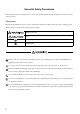
Essential Safety Precautions This manual describes safety instructions for correct use of the FP unit. Please keep this manual close at hand and refer to it when necessary. Safety Icons Throughout this manual, these icons provide essential safety information for FP operation procedures requiring special attention. These icons indicate the following levels of danger: Indicates situations where severe bodily injury, death or major equipment damage can occur.
In a situation that a detection function for the backlight burnout has been ineffective, if a burnout of the backlight happened, unlike in an extinction condition of the backlight of FP, the touch panel is still active. If an operator fails to notice that the backlight is burned out and touches the panel, a potentially dangerous machine miss-operation can occur. Therefore, do not set up switches on the touch panel of an FP that are likely to cause human error or physical damage triggered by mis-operation.
Avoid restricting the FP’s natural ventilation, or storing and using the FP in an environment that will increase the FP’s internal temperature. Do not use the FP in areas where sudden, large changes in temperature may occur. These changes can cause condensation to form inside the unit, possibly causing an accident. Do not store or use the FP where chemicals (such as organic solvents, etc.) and acids can evaporate, or where chemicals and acids are present in the air.
Connecting the FP to a PC The FP-3710K Series is designed for the following resolutions. Series Full Resolution FP-3710K Series 1024×768 Be aware that some types of devices for image signal output may not be within the ranges specified in this document, and, therefore, cannot be connected to the FP. Also, if you change your PC’s Analog RGB/DVI-D board, there is the possibility that the new board may not be able to be connected to the FP. SEE 4.1.
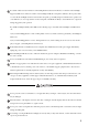
Information Symbols This manual uses the following icons: Indicates a warning or a product limitation. Be sure to follow the instructions given with this icon to ensure the safe operation of the FP. Contains additional or useful information. (1) (2) *1 SEE Indicates steps used to accomplish a given task. Be sure to follow these steps in the order they are written. Indicates useful or important supplemental information. Indicates pages containing related information.
FP-3710K Series Package Contents The FP unit’s packing box contains the items listed below. Please check to be sure each item is included and is not damaged.
Main Features FP-3710K Series displays are equipped with the following features. JFP-3710K Series • High Quality TFT Color LCD Display This unit is equipped with a 15.0 inch TFT type color LCD. Its superior brightness and wide viewing angle, not found in ordinary laptop-type TFT LCDs, widens your scope of applications. The screen's maximum resolution is 1024(H) × 768(V) pixels and can display 16,770,000 colors.
What is IP65f? This unit’s protection rating of IP65f is actually a composite code, consisting of the internationally recognized British “Ingress Protection” standard (BS EN 60529:1992) - “IP65”, and the standard developed by the Japanese Electronics Manufacturer’s Association (JEM) - “f”. This code is used in this manual to identify a given product’s degree of structural resistance to a variety of environmental elements and thus, prevent problems or accidents related to the inappropriate use of a product.
Installation prerequisites for standards • UL listed products Industrial Control Equipment refer to UL508 see [a] in the “Product List“ Suitable for use in Class I, Division 2, Groups A, B, C, and D Hazardous (classified) locations, or Non-Hazardous Locations. refer to ANSI/ISA 12.12.01 see [b] in the “Product List“ Process Control Equipment refer to CSA-C22.2 No.
• Suitable for use in Class I, Division 2, Groups A, B, C, and D Hazardous Locations only. • WARNING: Explosion hazard - substitution of components may impair suitability for Class I, Division 2. • WARNING: Explosion hazard - do not disconnect equipment while the circuit is live or unless the area is known to be free of ignitable concentrations.
CE Marking The FP-3710K Series are CE marked products complying with both the EMC Directive and low-voltage directive. For the detailed information on CE Marked, be downloaded and refer the Declaration of Conformity from Pro-face Home Page. Home Page URL http://www.pro-face.com/ FCC Statement United States FCC Part 15, Subpart B, Class A EMI Compliance Statement: NOTE: This equipment has been tested and found to comply with the limits for a Class A digital device, pursuant to part 15 of the FCC Rules.
Table of Contents Preface ...................................................................................................................... 1 Essential Safety Precautions ......................................................................... 2 Connecting the FP to a PC ............................................................................ 5 Information Symbols ...................................................................................... 6 FP-3710K Series Models ......................
Chapter 5 Installation and Wiring 5.1 Installation....................................................................................................... 5-2 5.1.1 Installation Procedures ................................................................. 5-2 5.2 Wiring.............................................................................................................. 5-7 5.2.1 Connecting the Power Cord.......................................................... 5-7 5.2.2 The USB Cable Clamp .....
9.2.1 Error Message List ........................................................................ 9-7 Chapter 10 Maintenance 10.1 Regular Cleaning .......................................................................................... 10-2 10.1.1 Cleaning the Display ................................................................. 10-2 10.1.2 Replacing the Installation Gasket.............................................. 10-3 10.2 Periodic Check Points...................................................
16
1 System Design 1. FP-3710K Series 2.
FP-3710K Series User Manual 1.1 FP-3710K Series The FP can be connected to Pro-face’s PS-2000B, PS-3000B, PS4000 series, PL3000 Series or to a Windows® compatible PC. For image signal connection, cables vary depending on a device to be connected. 1.2 Cables for connecting with computer (page1-3) SEE FP unit Front Side USB I/F *1 For downstream port of FP’s embedded USB-HUB (Type-A connector) Touch Panel transmission Peripherals complied with USB2.0/1.
Chapter 1 System Design 1.2 Cables for connecting with computer This section describes cables to connect the FP with a computer.
FP-3710K Series User Manual 1-4
2 Optional Equipment 1.
FP-3710K Series User Manual 2.1 Optional Equipment All optional items listed below are products of Digital Electronics Corporation. 2.1.1 Cables For image signal connection, cables vary depending on a device to be connected. SEE 1.2 Cables for connecting with computer (page1-3) Product Name Model No. Description RS-232C Cable FP61V-IS00-O Serial interface cable (5m) used for touch panel data transmission between the host and the FP. This is a straight Dsub9 pin female cable.
Chapter 2 Optional Equipment Optional Cable Diagrams FP PC 1 Analog R Input 1 RED IN RED VIDEO 2 Analog G 3 Analog B 4 Reserved - 4 5 Digital ground - 5 6 Return R - 6 7 Return G - 8 Return B - 9 Reserved - 10 Digital ground - 1 Output RED VIDEO Input 2 GRN IN GRN VIDEO Input 3 BLU IN BLU VIDEO NC NC 4 GND GROUND 5 RED GND GROUND RED 7 GRN GND 8 BLU GND 9 NC 10 1 2 Output GRN VIDEO 2 3 Output BLU VID
FP-3710K Series User Manual PC FP 1 2 3 4 5 6 7 8 9 10 11 12 13 14 15 16 17 18 19 20 21 22 23 24 TMDS DATA2TMDS DATA2+ TMDS DATA2 SHIELD NC NC DDC Clock DDC Data NC TMDS DATA1TMDS DATA1+ TMDS DATA1 SHIELD NC NC NC GND(+5V) Hot Plug Detect TMDS DATA0TMDS DATA0+ TMDS DATA0 SHIELD NC NC TMDS CLOCK SHIELD TMDS CLOCK+ TMDS CLOCK- FG FG Input Input Input Input Input - Input Input Input Input - 1 2 3 4 5 6 7 8 9 10 11 12 13 14 15 16 17 18 19 20 21 22 23 24 TMDS DATA2
Chapter 2 Optional Equipment FP SIO cable PC 1 CD Output 1 CD CD 1 Input CD 1 2 RD Output 2 RD RD 2 Input RD 2 3 SD Input 3 SD SD 3 Output SD 3 4 DTR Input 4 DTR DTR 4 Output DTR 4 5 GND - 5 GND GND 5 - GND 5 6 DSR Output 6 DSR DSR 6 Input DSR 6 7 RS Input 7 RS RS 7 Output RS 7 8 CS Output 8 CS CS 8 Input CS 8 9 NC - 9 NC RI 9 Input RI 9 FG FG - FG FG FG FG Signals and s
FP-3710K Series User Manual 2.1.2 Maintenance Parts Product Name Installation Fasteners 2.1.3 Model No. CA3-ATFALL-01 Description Metal installation fasteners. (4 fasteners/set) Installation Gasket CA7-WPG15K-01 Replacement installation gasket, used when installing the FP. Same as the FP's original gasket. Screen Protection Sheet CA3-DFS15-01 Disposable and dirt resistant sheet for the FP's screen. The FP's touch panel can be used with this cover sheet attached.
3 Part Names and Functions 1.
FP-3710K Series User Manual 3.1 FP-3710K Series A:TFT Color LCD The display monitor for your host unit. Front B:Touch Panel Allows you to switch screens or write data to the host. M N L L O P Q R J I K A,B C:Power Connector (socket) Provides the input and ground terminals for a power cable. D:Setting Switch By opening the cover, the Dip switches and slide switch are seen. Each switch can set a operation mode. SEE 6.
Chapter 3 Part Names and Functions K:Function Keys The character or the function is input. Front L:Special Function Keys The character or the special function is input. M N L L O P Q R M:F/A Key Function/Alpha key. The function input is switched to the character input. It becomes a character input because of the LED lighting. N:Window Keys O:Ten Keys J I K A,B P: Cursor Keys Q:Enter Key R:Mouse Pointer Two button mouse.
FP-3710K Series User Manual 3-4
4 Specifications 1. FP-3710K Series This chapter describes the general, functional and interface specifications of the FP as well as its dimensions.
FP-3710K Series User Manual 4.1 FP-3710K Series 4.1.1 General Specifications Electrical specifications Power Supply Items Specifications Rated Voltage AC100 to 240V Allowable Voltage AC85 to 264V Rated Frequency 50 / 60Hz Rated Frequency Range 40Hz to 72 Hz Allowable Voltage Drop 1 cycle or less (Voltage drop interval must be 1s or more) Current Consumption In-Rush Current AC 100V 1.1A or less (TYP 0.75A) AC 240V 0.7A or less (TYP 0.
Chapter 4 Specifications Structural specifications Items Installation Grounding Structure External Dimensions Specifications 100 Ω or less, or your country’s applicable standard. Rating*1: Equivalent to IP65f (JEM 1030) W488mm [19.21in.] × H367mm [14.45in.] × D63mm [2.48in.] Weight Cooling Method *1 Approx. 8.0kg [17.6lb] Natural air circulation The front face of the FP unit, installed in a solid panel, has been tested using conditions equivalent to the standards shown in the specification.
FP-3710K Series User Manual 4.1.2 Functional Specifications Performance Items Specifications Graphics XGA (1024 × 768) Display Unit 15 inch TFT XGA Type Resistive Film (Analog) Resolution 1024 × 1024 Service Life 1,000,000 times or more Interface Serial Interface (RS-232C) USB Interface (Type-B connector) No.
Chapter 4 Specifications 4.1.3 Interface Specifications Analog RGB Interface Input signal type Analog RGB Input signal characteristic Image signal: analog RGB Synchronous signal: TTL level, negative polarity or positive polarity Scanning type: non-interlaced Setting via OSD (On Screen Display) • CONTRAST • H-POSITION • H-size • DIMMER (BACKLIGHT) • ALL RESET (DEFAULT) • BRIGHTNESS • V-POSITION • PHASE • SHARPNESS Display Area The number of dots (pixels) displayed are as follows. Size H.Sync.
FP-3710K Series User Manual Analog RGB Interface Pin Assignments and Signal Names Pin No. 1 2 3 4 5 6 7 8 9 10 11 12 Analog R Analog G Analog B Reserved Digital grounding Return R Return G Return B Reserved Digital grounding Reserved DDC DATA 13 H. SYNC 14 V.
Chapter 4 Specifications DVI-D Interface Input signal type Setting by OSD (On Screen Display) DVI-D • CONTRAST • SHARPNESS • ALL RESET (DEFAULT) • BRIGHTNESS • DIMMER (BACKLIGHT) DIsplay Area The number of dots (pixels) displayed are as follows: Size H.Sync. (kHz) V.Sync. (Hz) Dot Clock (MHz) 640 × 400 24.827 56.420 21.053 640 × 400 31.469 70.000 25.175 640 × 480 31.469 59.992 25.175 640 × 480 37.500 75.000 31.500 640 × 480 35.000 66.670 30.240 720 × 400*1 31.469 70.
FP-3710K Series User Manual DVI-D Interface Pin Assignments and Signal Names Pin No. 1 2 3 4 5 6 7 8 9 10 11 12 Signal Name TMDS DATA2TMDS DATA2+ TMDS DATA2 SHIELD NC NC DDC Clock DDC Data NC TMDS DATA1TMDS DATA1+ TMDS DATA1 SHIELD NC Pin No. 13 14 15 16 17 18 19 20 21 22 23 24 Signal Name NC NC GND Hot Plug Detect TMDS DATA0TMDS DATA0+ TMDS DATA0 SHIELD NC NC TMDS CLOCK SHIELD TMDS CLOCK+ TMDS CLOCK- Pin Location 17 1 24 8 Connector...........................
Chapter 4 Specifications Serial Interface Baud rate : 9600 bps Data length : 8 bits Serial Interface Parity : none Stop bit :1 Flow control : None RS-232C Interface Pin Assignments and Signal Names Pin No.
FP-3710K Series User Manual USB Interface (Up-stream port) USB 2.0/1.1 compliant • Low (1.5 Mbps) Supported speed • Full (12 Mbps) • Hi (480 Mbps) USB Interface Communication distance (Max): 5m The USB Interface is supported by a host PC equipped with Windows®2000(SP4) or later, or Windows®XP(SP1) or later. USB Interface Pin Assignments and Signal Names Pin No.
Chapter 4 Specifications Front USB Interface (Down-stream port) USB 2.0/1.1 compliant • Low (1.5 Mbps) Supported speed • Full (12 Mbps) • Hi (480 Mbps) USB Interface Power supply voltage: 5 VDC ± 5%, Output current: 500mA (max.) Communication distance (Max): 5m Connectable USB: 127*1 Connection phase: 6 phases*1 *1 It is a number of totals seen from host PC. It is different according to the connected situation. Two USB-HUB are built into the FP.
FP-3710K Series User Manual 4.1.4 Dimensions External Dimensions Unit: mm [in.] 441 [17.36] center of unit Rear Side Front Dimensions with installation fasteners Unit: mm [in.] 461.4 [18.17] 352 [13.86] 441 [17.36] 488 [19.21] Top 10 [0.39] 63 [2.48] (3 [0.12]) Side Front Bottom 4-12 333.4 [13.13] center of unit 313 [12.32] center of display area 367 [14.45] 21 [0.83] 26.5 [1.04] Side [2.95] [3.94] 100 8 [0.31] 75 8-M4 Effective Screw Depth 7 [0.28] 15 [0.
Chapter 4 Specifications Dimensions with Cables 29.7 [1.17] 45.3 [1.78] Side 43.3 [1.70] 43.4 [1.71] 10.3 [0.41] Unit: mm [in.] Side Rear Bottom • All the above values are designed in case of cable bending. The dimensions given here are representative values depending on the type of connection cable used. Therefore, they are all intended for reference only. Installation Fasteners Unit: mm [in.] 11[0.43] 16 [0.63] 16.6 [0.65] 31 [1.22] ∅10[0.
FP-3710K Series User Manual Panel Cut Dimensions Unit: mm [in.] r ≤ 3 [0.12] [12.34 +0.04 ] -0 441.5 +1.0 [17.38 +0.04 ] -0 -0 +1.0 313.5 -0 Panel • Panel thickness should be between 1.6mm [0.06in.] and 10mm [0.39in.]. Decide the panel's thickness based on the level of panel strength required. • Check that the installation panel or cabinet's surface is flat, in good condition and has no jagged edges.
5 Installation and Wiring 1. Installation 2. Wiring This chapter explains the installation method and the wiring method for the FP.
FP-3710K Series User Manual 5.1 Installation 5.1.1 Installation Procedures Follow the steps given below when installing the FP. Check the Installation Gasket’s Seating It is strongly recommended that you use the installation gasket, since it absorbs vibration in addition to repelling water. Place the FP on a level surface with the display panel facing downward. Check that the FP’s installation gasket is seated securely into the gasket’s groove, which runs around the perimeter of the panel’s frame.
Chapter 5 Installation and Wiring Creating a Panel Cut Create the correct sized opening required to install the FP, using the installation dimensions given. The installation gasket, installation fasteners and attachment screws are all required when installing the FP. Decide the panel's thickness based on the level of panel strength required. SEE Panel Cut Dimensions (page4-14) • Check that the installation panel or cabinet’s surface is flat, in good condition and has no jagged edges.
FP-3710K Series User Manual • Be sure that the ambient operating temperature and the surrounding operating humidity are within their designated ranges. (When installing the FP in a cabinet or an enclosure, “Ambient operation temperature” indicates both the panel face and cabinet or enclosure's internal temperature.). Unit: mm [in.] 100 [3.94] 100 [3.94] 30 [1.18] Panel Face 30 [1.
Chapter 5 Installation and Wiring Installing the FP (1) Insert the FP into the panel cut, as shown here. Panel Panel Cut FP Panel Side (2) Insert the installation fasteners into the FP’s insertion 12 slots.
FP-3710K Series User Manual Installation panel Hook (3) Insert each of the fasteners as shown below. Be sure to pull the fastener back until it is flush with the rear of the attachment hole. (4) Tighten the fastener screws equally in a diagonal pattern by using a Phillips screw driver. When tightening them, slowly increase the torque. (12 places) • Do not use too much force, since it may damage the FP unit. A torque of only 0.8 N•m, are sufficient to tighten these screws.
Chapter 5 Installation and Wiring 5.2 Wiring 5.2.1 Connecting the Power Cord To avoid an electric shock, when connecting the FP’s power cord terminals to the power terminal block, confirm that the FP’s power supply is completely turned OFF, via a breaker, or similar unit. To avoid the dangers of fire, electric hazards and equipment damage, be sure to use only the specified voltage when operating the FP.
FP-3710K Series User Manual Power connector specification L AC Input Terminal-live line N AC Input Terminal-neutral line FG Ground Terminal connected to the FP chassis L N FG Power Cable Joint • Kind of power cord is FKC 2,5/3-STF-5,08 which are Phoenix Contact*1 products. *1 Please contact Phoenix Contact for the details. Wiring Use the following wiring for FP. Those are Phoenix Contact products. Recommended Drivers SZS 0.6X3.5 (1205053) AI 0.
Chapter 5 Installation and Wiring (4) After inserting all three pins, insert the Power Plug into the Power Connector at FP. Fix the plug with two(2) minus screws. • Confirm that all wires are connected correctly. • The torque required to tighten these screws is 0.5 N•m - 0.6 N•m. • To prevent the possibility of a terminal short, use a pin terminal that has an insulating sleeve. 5.2.
FP-3710K Series User Manual 5.2.3 Connecting the Power Supply • If the power supply voltage exceeds the FP unit’s spec- Twisted-pair cord Constant Voltage Transformer FP Unit FG ified range, connect a constant voltage transformer. SEE 4 Specifications (page4-1) • For between the line and ground or between the lines, select a power supply that is low in noise. If there is an excess amount of noise, connect an insulating trans- Twisted-pair cord FP Unit Insulating Transformer former.
Chapter 5 Installation and Wiring 5.2.4 Precautions: Grounding (a) Exclusive grounding (BEST) • Connect the FP’s FG terminal to an exclusive ground. [diagram (a) - Grounding resistance of under 100Ω.] FP Unit Other Equipment • If exclusive grounding is not possible, use a common (b) Common grounding (OK) connection point. [diagram (b)] FP Unit Other Equipment • The grounding wire should have a cross sectional area greater than 2mm2.
FP-3710K Series User Manual 5-12
6 Setting up and Adjusting the FP unit 1. Operation Mode Setup 2. Screen Display Adjustment This chapter describes the settings of the operation mode and the OSD.
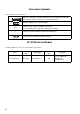
FP-3710K Series User Manual 6.1 Operation Mode Setup 6.1.1 Preset Settings and Adjustments for Dip Switch and Slide Switch The Dip Switches and Slide Switch are located in the bottom of the FP unit. Loosen the screws of the cover with a Phillips head screwdriver and then remove the cover. After setting the dip switches and slide switches, reinstall the cover and screws with the screwdriver. The tightening torque for those screws is 0.5 to 0.6 N•m.
Chapter 6 Setting up and Adjusting the FP unit The factory default for the FP unit’s Dip Switches and Slide Switch are as follows. • Only the settings when the power supply is turned on is effective to the Dip Switches and the Slide Switch. After changing the settings of the Dip Switches and the Slide Switch, be sure to restart your FP unit.
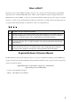
FP-3710K Series User Manual 6.2 Screen Display Adjustment 6.2.1 Calibration of OSD Display Position You can operate the FP screen menus via the touch panel, and adjust screen image display to a minute level. The feature is called OSD (On Screen Display). This section describes items and functions that can be set with OSD.
Chapter 6 Setting up and Adjusting the FP unit (2) Main Menu Using the OSD Icons on the screen are used to operate the OSD. When you start up the OSD, the top menu displays. Touching the icon of the item you want to adjust displays its submenu or setting change screen. In the setting change screen, icons are used to change the setting. To set the setting, press the button. Press the button to save the defined settings. “Ver.*.**” indicates the version of the OSD.
FP-3710K Series User Manual 6.2.2 OSD Setting Icons Item 6-6 Function Color Settings Adjusts the contrast and the brightness. Screen Settings Adjusts the display position of the screen. Custom Display Adjusts Sharpness and the backlight brightness. System Settings Changes settings such as activating the click sound. All Reset Resets the current OSD value to the default value. Input Source Switches Analog RGB and DVI-D. Auto Adjust Automatically adjusts the display position of the screen.
Chapter 6 Setting up and Adjusting the FP unit 6.2.3 OSD Setting Item Details Main Menu Color Settings Selection of the change item Contrast Adjusts the contrast. R.Contrast Adjusts the R.contrast. G.Contrast Adjusts the G.contrast. B.Contrast Adjusts the B.contrast. Brightness Adjusts the Brightness. Adjustment button Applies the setting and then returns to the top menu. Cancels the setting and then returns to the top menu. Screen Settings Selection of the change item Adjustment button H.
FP-3710K Series User Manual System Settings Selection of the change item Adjustment button Click Tone Enables/disables the click sound. With this parameter, the sound level can also be adjusted. (Default value: OFF ) 720x400 Mode When an input data resolution of 720 x 400 is used in the VGA text mode, set this parameter to ON. For other resolutions, set this parameter to OFF.
Chapter 6 Setting up and Adjusting the FP unit All Reset Resets all the settings and then returns to the top menu. Cancels the setting and then returns to the top menu. Input Source Switches Analog RGB and DVI-D, and quits the OSD Cancels the setting and then returns to the top menu. Auto Adjust (Analog RGB only) Applies the setting and then returns to the top menu. Cancels the setting and then returns to the top menu.
FP-3710K Series User Manual 6-10
7 Touch Panel Data 1. Touch Interface Data This chapter describes the outline of the software to input the touch panel data to the host computer.
FP-3710K Series User Manual 7.1 Touch Interface Data The FP-3710K Series units use an analog type touch panel. This touch panel needs a calibration program to adjust the actual touch position. The display resolutions is 1024 × 768. The screen display origin point is at the upper left corner of the screen. Therefore, a mouse emulation software to convert the touch coordinates to display coordinates is needed. • For details on the mouse emulation software, refer to "Related Software". SEE 2.1.
Chapter 7 Touch Panel Data (2) Data Format Touch Panel coordinate data is sent to the host using the following format. All data is in binary format. Header: 1 byte (11h= touched; 10h = released) X coordinate: 2 bytes (0 to 3FFh) Y coordinate: 2 bytes (0 to 3FFh) X coordinate Y coordinate 10h 11h Added when touch is released. If the coordinate (X=23(11h), Y=500(1F4h)) is touched and moved to the coordinate (X=63(3Fh), Y=250(FAh)).
FP-3710K Series User Manual 7-4
8 Keyboard Operation 1. About KeyPad Module 2. Features of KPM 3. Scan Code List 4. Configuring the Keyboard Layout 5. Restrictions This chapter describes the features of KeyPad Module, which is included with the FP-3710K Series.
FP-3710K Series User Manual 8.1 About KeyPad Module KeyPad Module (hereafter referred to as "KPM") is a keyboard module that is included with the FP-3710K Series. You can operate the panels using the keypad and mouse pointer in the front panel of KPM. Special function keys Function keys Using KPM, you can input text and operate shortcuts (key codes assigned to each application) in user applications running on Host.
Chapter 8 Keyboard Operation 8.2 Features of KPM KPM has function keys (F1/K to F20/*) and special function keys (PF1/A to PF20/~). These are used not only for text input but also as shortcut keys for applications. They can be used as shortcut keys by assigning key codes to each key in user applications. Features of function keys and special function keys (About input mode) In the input mode for function keys and special function keys, each has a Function mode and Alpha mode.
FP-3710K Series User Manual 8.3 Scan Code List You can use shortcuts by assigning key codes to each key in user applications. Each key except for the [F/A] key can have key codes assigned to it for an application. Assign the key code based on the task. Function keys/Special function keys (Function mode) In Function mode, each function key and special function key can be assigned a function from F1 to F40.
Chapter 8 Keyboard Operation Function keys/Special function keys (Alpha mode) In Alpha mode, each function key and special function key can be assigned a character from A to Z and symbols. (Refer to the following table.
FP-3710K Series User Manual 8.4 Configuring the Keyboard Layout KPM is configured so that it will operate normally with US keyboard layout. When inputting text in Alpha mode, make sure that the keyboard layout is set to US. For the procedure to configure the keyboard layout, refer to the following. • Immediately after the Japanese language version of Windows® (preinstalled or otherwise) is installed, the keyboard layout is set to Japanese.
Chapter 8 Keyboard Operation (3) When the [Text Services and Input Languages] dialog box appears, select [Add] in [Installed services]. (4) The [Add input language] dialog box appears. Select the desired language from the [Input language] combo box. In [Keyboard layout/IME], select the keyboard layout of the keyboard to be attached and click [OK].
FP-3710K Series User Manual (5) When the [Text Services and Input Languages] dialog box appears again, select the language from [Default input language]. Next, click [Apply] and then [OK]. Using this setting the selected language will be set as the default language. Configuring keyboard layout in Windows® 2000 8-8 (1) Select [Control Panel] and then [Regional Options]. (2) In the [Input Locales] tab, click [Add] in [Switch between input locales].
Chapter 8 Keyboard Operation (3) The [Add Input Locale] dialog box appears. Select a language from [Input locale]. In [Keyboard layout/IME], select the keyboard layout of the keyboard to be attached and click [OK]. (4) The [Regional Options] window appears again. From [Installed input locales], select the language selected earlier, and click [Set as Default]. Click [Apply] and then [OK]. Using this setting the selected language will be set as the default language.
FP-3710K Series User Manual Using KPM to Operate Applications from Shortcuts Assign a key or key code to KPM for each user application to enable shortcut operations. • Key codes can be assigned to all keys except the F/A key; however, it is recommended to assign key codes to function keys and special function keys. (1) Create a shortcut to an application, folder or file that you want to assign a shortcut operation.
Chapter 8 Keyboard Operation (4) Select the [Shortcut Key] tab. Press the function key or special function key you want to assign a shortcut operation. The [Shortcut Key] field displays an automatically-selected combination of function key(s) or special function key(s). • For the details of combination of function key(s) or special function key(s), refer to the following section. SEE (5) 8.3 Scan Code List (page 8-4) Click the [OK] button.
FP-3710K Series User Manual Key combinations and key functions in Function mode By combining F1 to F10, Shift, Ctrl, and Alt, you can create key functions unique to KPM or have the same operations as F11 to F40. For details about each key combination and the key function that is output, refer to the following. • In Function mode, when PF14/^ is pressed, the code for Alt+F4 on a commercially available USB keyboard is output.
Chapter 8 Keyboard Operation 8.5 Restrictions • When inputting in Alpha mode with a keyboard that does not have US keyboard layout, some of the key labels will differ from what is output. Always use US keyboard layout except when inputting languages other than English. • In KPM, the following key codes on a 101-key keyboard cannot be output.
FP-3710K Series User Manual 8-14
9 Troubleshooting 1. Troubleshooting 2.
FP-3710K Series User Manual 9.1 Troubleshooting 9.1.1 Possible Device Problems This chapter explains the main method of dealing with the trouble in the use of the FP. • For problems other than problems of the FP, please refer to the manual of each equipment. Possible types of trouble while using this unit are as follows. No display • No display appears after the unit is switched on. • The screen disappears during standard operation. • The screen does not display normally.
Chapter 9 Troubleshooting 9.1.2 No Display When the screen does not display when powering up, or if the screen turns OFF by itself, use the flowchart below to find an appropriate solution. No Screen Display YES Does the backlight (CCFL) light up? NO NO Is it using the correct power voltage? Connect the appropriate voltage. SEE 4 Specifications (page4-1) YES Turn OFF the power switch. Is the power supply cable connected properly to the unit? NO Fix the power cable connection.
FP-3710K Series User Manual NO Is the PC operating? Start the PC. YES Are the FP output settings the same as the PC's frequency and resolution? NO Set the FP output settings so that they match the PC’s frequency and resolution. YES NO Is the RGB cable/ DVI-D cable connected correctly? Connect the RGB cable/DVI-D cable correctly. SEE Optional Cable Diagrams (page2-3) YES Does the screen display though display is not normal. YES NO There is a problem with the FP unit.
Chapter 9 Troubleshooting 9.1.3 Touch Panel Does Not Respond When the touch panel does not react, or its reaction is very slow after it is pressed, follow the flowchart below to find the origin of the problem and the appropriate solution. Touch panel is not working Is the Mouse Emulation Software installed in PC (Host)?. NO Install the Mouse Emulation Software. For details, Refer to the “Installation Guide” (PDF file) which is supplied with the Mouse Emulation Software.
FP-3710K Series User Manual 9.1.4 Trouble of keypad operation Problem I want to know what the LED indicator indicates. Countermeasure and reference page To tell the difference between Function mode and Alpha mode in KPM. SEE When inputting text in KPM, the text output is different from the text label. Is the keyboard layout set to US? KPM is configured to operate normally with US keyboard layout. When inputting text in Alpha mode, make sure US keyboard layout is set.
Chapter 9 Troubleshooting 9.2 Error Message This section explains the messages that appear when an error has occurred in the FP unit during RUN mode.The problem causing the error message and its related countermeasure are explained in the table below. (Only the latest error message will appear on the FP screen) 9.2.1 Error Message List Error Message Problem Signal timing has been input that is not compatible with the FP unit.
FP-3710K Series User Manual 9-8
10 Maintenance 1. Regular Cleaning 2. Periodic Check Points 3. Backlight Replacement This chapter indicates necessary cautions and inspection criteria to maintain your FP.
FP-3710K Series User Manual 10.1 Regular Cleaning 10.1.1 Cleaning the Display When the display surface or frame OK! become dirty, use a soft cloth moistened with neutral detergent to wipe away any dust or stains. Neutral detergent NG! Display Do not clean the unit with thinner, organic solvents, or strong acids. Thinner Organic solvent Strong acid Do not use sharp or hard objects, such as a mechanical pencil or screwdriver, to push on the display. This could damage the unit.
Chapter 10 Maintenance 10.1.2 Replacing the Installation Gasket The installation gasket protects the FP and improves its water resistance. For instructions on installing the FP unit's gasket, refer to the following page. SEE 5 Installation and Wiring (page5-1) • A gasket which has been used for a long period of time may have scratches or dirt on it, and could have lost much of its water resistance. Be sure to change the gasket at least once a year, or when scratches or dirt become visible.
FP-3710K Series User Manual • The gasket must be inserted correctly into the groove for the FP unit’s moisture resistance to be equivalent to IP65f. • Since the gasket is flexible but not elastic, be careful not to stretch it unnecessarily, as doing so could tear the gasket. • Be sure the gasket's seam is not inserted into any of the unit's corners, only in the straight sections of the groove. Inserting it into a corner may lead to its eventually tearing.
Chapter 10 Maintenance 10.2 Periodic Check Points To keep your FP unit in its best condition, please inspect the following points periodically.
FP-3710K Series User Manual 10.3 Backlight Replacement 10.3.1 FP-3710K Series FP units use a CFL, long-life type backlight. The actual life of the backlight however, will vary depending on the FP’s operating conditions. It is recommended that it be replaced periodically. The service life (half brightness life) of the backlight when it is lit continuously at room temperature is as described below. 50,000 hours --- approx. 5.
Chapter 10 Maintenance Replacing CA7-BLU15-01 • The backlights are located at the top and bottom of the LCD. These two lights must be replaced together. Be sure to wear gloves when exchanging the backlight, and follow the following procedures. (1) Turn OFF the power switch of the FP and remove the power cable. (2) Remove the FP unit from the equipment (panel etc.) to which the unit has been incorporated, and place the FP unit on a flat, level surface facing the display face downwards.
FP-3710K Series User Manual (6) Loosen the upper and lower backlight attachment screws. Backlight attachment screw (7) Disconnect the cable of the backlight unit from the backlight connector on the inverter board, and remove it from the cable clamp. Cable Cable Clamp (8) 10-8 Inverter Board Lift the LCD holder up as shown in the figure and pull the cable in the direction of the arrow. The backlight unit can be drawn out from the port.
Chapter 10 Maintenance (10) Lower the LCD holder, connect the backlight cables to the backlight connectors, and secure the cables with the clamp. (Repeat the steps (7) through (10) for the other backlight unit.) • Be sure to insert the cable into the connector securely. Failure to do so may damage the connector. • To prevent the cable from being caught when reassembling the FP unit, be sure to secure the backlight cables with the clamp before installing the rear cover.
FP-3710K Series User Manual 10-10