
Manual

FP-3710K Series User Manual
4-8
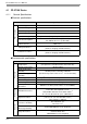
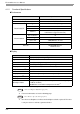
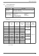
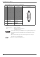
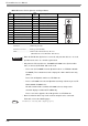
DVI-D Interface Pin Assignments and Signal Names
Connector...........................DVI-D 24-pin male
Connector set screw...........Inch type (#4-40 UNC)
Cable..................................DVI-D cable manufactured by Pro-face
(FP-DV01-50 <5 m>, FP-DV01-100 <10 m>)
Pin
No.
Signal Name
Pin
No.
Signal Name Pin Location
1 TMDS DATA2- 13 NC
2 TMDS DATA2+ 14 NC
3 TMDS DATA2 SHIELD 15 GND
4 NC 16 Hot Plug Detect
5NC17TMDS DATA0-
6 DDC Clock 18 TMDS DATA0+
7 DDC Data 19 TMDS DATA0 SHIELD
8NC20NC
9 TMDS DATA1- 21 NC
10 TMDS DATA1+ 22 TMDS CLOCK SHIELD
11 TMDS DATA1 SHIELD 23 TMDS CLOCK+
12 NC 24 TMDS CLOCK-
• When the DVI-D cable by Pro-face is not used, and your own cable etc. are used,
operation to the noise etc. cannot be guaranteed.
• Only when the FP-3710 K Series, PS-2000B or PL3000 Series (Revision B or
more) is connected, FP-DV01-100 can be used.
• Please turn on PS-2000B’s internal dipswitch 4 when use FP-DV01-100 with
PS-2000B. (The resolution that can be displayed is 1024 x 768 Become only
(XGA). )
Please turn off dipswitch 4 when use FP-DV01-50.
• Please set PL3000 Series internal dipswitch 5 to z sign side when you use FP-
DV01-100 with PL3000 Series.
We will recommend the resolution of PL3000 Series to change to the
maximum display resolution of FP additionally.
Please set it on the opposite side of z sign when use FP-DV01-50.
• Above-mentioned cables may not be used for computers to be connected.
For details, refer to the following page.
SEE
1.2 Cables for connecting with computer (page1-3)
1
8
24
17