/7 6HULHV +DUGZDUH 0DQXDO
Preface Thank you for purchasing Pro-face’s LT3000 Series Graphic Logic Controller Interface (Hereafter referred to as the “LT unit”). Before operating your LT unit, be sure to read this manual to familiarize yourself with the LT unit’s operation procedures and features. NOTICE 1. Copying this manual’s contents, either in whole or in part, is prohibited without the express permission of Digital Electronics Corporation, Japan. 2.
Essential Safety Precautions All safety-related procedures stated in this document must be followed to operate the LT correctly and safely. Be sure to read this and any related documents thoroughly to understand the correct operation and functions of the LT unit. Safety Icons Throughout this manual, these icons provide essential safety information for LT operation procedures requiring special attention.
Design a circuit that will supply power to the LT unit’s I/O before starting up the LT. If the LT unit’s internal program enters RUN mode prior to the I/O unit’s load control power turning ON, an incorrect output (signal) or malfunction could cause an accident. Design a user program that ensures the safety of the user’s system, in the event of a LT display or control error, or either a data transmission error or power failure between the LT and a connected unit.
Handling Do not disassemble or modify the LT unit. Doing so may cause a fire or an electric shock. Do not operate the LT in an environment where flammable gases are present, since it may cause an explosion. Wiring To prevent electrical shock or equipment damage, unplug the LT unit’s power cord from the power supply prior to installing or wiring the LT. To prevent an electric shock be sure to disconnect your LT unit’s power cord from the power supply before wiring the LT.
Wiring Be sure to ground the LT unit’s FG wire separately from other equipment FG lines. Also, be sure to use a grounding resistance of 100Ω or less and a 2mm2 [0.0062inch2] or thicker wire, or your country’s applicable standard. Otherwise, electric shock or malfunctions may result. Be sure to use only the designated torque to tighten the LT unit’s terminal block screws. If these screws are not tightened firmly, it may cause a short-circuit, fire or incorrect unit operation.
Do not use paint thinner or organic solvents to remove dirt or oil from the LT unit’s surface. Instead, use a soft cloth moistened with a diluted neutral detergent. Do not use or store the LT in areas with direct sunlight, since the sun’s ultraviolet rays may cause the LCD’s quality to deteriorate. Do not store the LT in an area where the temperature is lower than that recommended in the LT unit’s specifications. Doing so may cause the LCD display’s liquid to congeal, which can damage the LCD.
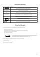
Information Symbols This manual uses the following icons: Indicates a warning or a product limitation. Be sure to follow the instructions given with this icon to ensure the safe operation of the LT. Screen Editor Indicates the GP-Pro EX software. PLC Abbreviation for Programmable Logic Controller. Logic program Indicates a ladder program created with the GP-Pro EX. * Indicates useful or important supplemental information. Contains additional or useful information.
LT3000 Series Model Name Indication Model name LT 3 * ** - * 1 - *** - * A B A B C D E C D E 2 LT-3200 series (3.8-inch): QVGA (320 x 240 dots) 3 LT-3300 series (5.7-inch): QVGA (320 x 240 dots) 00 Standard machine 01 Low-cost machine A Monochrome Amber/ Red LCD L Monochrome LCD S STN color LCD T TFT color LCD D24 DC type power supply is used.
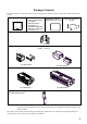
Package Contents The following items are included in the LT unit’s package. Before using the LT, please check that all items listed here are present.
Installation prerequisites for standards • UL listed products Industrial Control Equipment refer to UL508 see [a] in the “Product List“ Suitable for use in Class I, Division 2, Groups A, B, C, and D Hazardous (classified) locations, or Non-Hazardous Locations. refer to ANSI/ISA-12.12.01 see [b] in the “Product List“ Standard for Process Control Equipment refer to CSA-C22.2 No.
Be aware of the following items when building the LT into an end-use product: • The LT unit’s rear face is not approved as an enclosure. When building the LT unit into an end-use product, be sure to use an enclosure that satisfies standards as the end-use product’s overall enclosure. • The LT unit must be used indoors only. • Install and operate the LT with its front panel facing outwards. • If the LT is mounted so as to cool itself naturally, be sure to install it in a vertical panel.
CE Marking The following units are CE marked products complying with the EMC Directive. LT3201-A1-D24-K LT3300-S1-D24-K LT3300-T1-D24-K LT3300-L1-D24-K LT3301-L1-D24-K LT3201-A1-D24-C LT3300-S1-D24-C LT3300-T1-D24-C LT3300-L1-D24-C LT3301-L1-D24-C For the detailed information on CE Marked, be downloaded and refer the Declaration of Conformity from Pro-face Home Page. Home Page URL http://www.pro-face.
Contents Preface ...................................................................................................................... 1 Essential Safety Precautions..................................................................................... 2 Information Symbols.................................................................................................. 7 About the Manuals ....................................................................................................
2.2.2 Performance Specifications ................................................................................2-19 2.2.3 Interface Specifications .......................................................................................2-21 2.2.4 Wiring to the DIO Connector...............................................................................2-30 2.2.5 Dimensions .........................................................................................................
1 Overview 1. System Design 2. Accessories 3. Part Names and Functions This chapter describes peripheral devices that can be connected to LT Series units along with the name and functions of each part.
LT3000 Series Hardware Manual 1.1 System Design 1.1.1 LT-3200 Series The following diagram illustrates the standard range of items that can be connected to LT-3200 Series units.
Chapter 1 Overview Edit Mode Peripherals LT Unit (1) USB Transfer Cable CA3-USBCB-01 USB Port USB Memory Strage *1 (Commercial type) Serial Port USB-Serial (RS-232C) Conversion Cable CA6-USB232-01 RS-232C Cable*2 (Prepared by user) Personal Computer *3 (Commercial type) Screen Editor Software GP-Pro EX Modem*1 (Commercial type) Telephone lines LT Interfaces (1) USB Host Interface *1 For supported models, refer to Pro-face’s support site “Otasuke Pro!” (http://www.pro-face.com/otasuke/).
LT3000 Series Hardware Manual 1.1.2 LT-3300 Series The following diagram illustrates the standard range of items that can be connected to LT-3300 Series units.
Chapter 1 Overview LT Interfaces Temperature Controller (etc.) Interfaces (1) Ethernet Interface (10BASE-T/100BASE-TX) Not available with LT-3301L units (2) USB Host Interface (3) EX Module Interface (4) DIO Interface (5) Serial Interface (COM1) (RS-232C mode) (6) Serial Interface (COM1) (RS-422 mode) (7) RS-232C Port (8) RS-422 Port *1 *2 *3 For supported models, refer to Pro-face’s support site “Otasuke Pro!” (http://www.pro-face.com/otasuke/).
LT3000 Series Hardware Manual 1.2 Accessories All accessories listed here are produced by Digital Electronics Corporation. 1.2.1 USB Host Interface Product Name Model No. USB Transfer Cable CA3-USBCB-01 (2m) Downloads project data created with the Screen Editor via the LT unit’s USB I/F. USB Cable FP-US00 (5m) Connects a USB printer. (TYPE-B) USB Front Cable CA5-USBEXT-01 (1m) Extension cable attaching USB port to front panel. CA6-USB232-01 (0.
Chapter 1 Overview 1.2.3 Option Items Product Name Screen Protection Sheet Proective Cover 1.2.4 Model No. Corresponding LT CA6-DFS4-01 LT-3200 Series CA3-DFS6-01 LT-3300 Series CA4-DCMDL-01 LT-3300 Series Description Disposable, dirt-resistant sheet for the LT unit’s screen.
LT3000 Series Hardware Manual 1.2.5 EX Module (Expanded I/O Unit for LT3000 Series use) Up to two EX modules can be connected to the rear side of the LT-3200 series. Up to three EX modules can be connected to the rear side of the LT-3300 series. • As for EXM-DMM24DRF and EXM-ARI8LT, only one EX module can be connected to an LT. For the details, please read “EX Module Hardware Manual” downloaded from Pro-face's support site “Otasuke Pro!” (http://www.pro-face.com/otasuke/).
Chapter 1 Overview Analog Input Module Product Name Model No. Description EXM-AMI2HT 2-ch analogue Input Unit. (Voltage DC0 to 10V / Current DC4 to 20mA) EX module (4-ch Analog input / Temperature input EXM-AMI4LT module) 4-ch temperature Input Unit. (Voltage DC0 to 10V / Current DC4 to 20mA) Pt100/Pt1000/Ni100/Ni1000 EX module (8-ch Pt100/Pt1000 input module) 8-ch temperature Input Unit.
LT3000 Series Hardware Manual 1.3 Part Names and Functions 1.3.1 LT-3200 Series A: Status LED This LED indicates the LT’s status, e.g. power input, firmware RUN status or backlight condition. Also, indicates the status of logic program execution. Color Indicator A ON Front Green Flashing ON Red B C Orange Flashing Operation Mode (Drawing) Logic execution mode (when logic is enabled) OFFLINE - In operation RUN In operation STOP When power is turned on.
Chapter 1 Overview 1.3.2 LT-3300 Series A: Status LED This LED indicates the LT’s status, e.g. power input, firmware RUN status or backlight condition. Also, indicates the status of logic program execution. Color Indicator A ON Green Front Flashing ON Red Orange Right side D F G E Bottom H OFFLINE - In operation RUN In operation STOP When power is turned on.
LT3000 Series Hardware Manual 1-12
2 Specifications 1. LT-3200 Series 2. LT-3300 Series This chapter describes the general, functional and interface specifications of the LT as well as its part names and dimensions.
LT3000 Series Hardware Manual 2.1 LT-3200 Series 2.1.1 General Specifications Power Supply Electrical Specifications Input Voltage DC24V Rated Voltage DC19.2 to 28.8V Allowable Voltage Drop 10ms (max.) Power Consumption 18W (max.) In-Rush Current 30A (max.) Voltage Endurance AC1000V 20mA for 1 minute (between charging and FG terminals) Insulation Resistance DC500V 10MΩ (min.
Chapter 2 Specifications Installation Structural Specifications Grounding Grounding resistance of 100Ω 2mm2 or thicker wire, or your country’s applicable standard. (Same for FG and SG terminals) *1 Rating: Equivalent to IP65f NEMA #250 TYPE 4X/13 (Front surface at panel embedding) Feature size: All-in-one Installation configuration: Panel embedding Structure Cooling Method Natural air circulation Weight Approx. 1.0kg [2.2lb] max. (unit only) External Dimensions Panel Cut Dimensions *1 W130.
LT3000 Series Hardware Manual 2.1.2 Performance Specifications Performance Specifications Application*1 FLASH EPROM 6MB SRAM 128K byte Data Backup Used lithium battery for backup memory Interface DIO Interface AUX Interface/ Expansion Unit The interface to external I/O equipment Input/Output points: 12-point inputs, 6-point outputs Connector: 22 pins Interface for external additional unit only (such as communication equipment) (external) USB Host Interface Conforms to USB1.1. (TYPE-A conn.
Chapter 2 Specifications Display Specifications Display Type Monochrome Amber/ Red LCD Resolution W320 x H240 pixels Dot pitch W0.24mm [0.01in] x H0.24mm [0.01in] Effective Display Area W78.8mm [3.10in] x H59.6mm [2.35in] Color/Shade level Black and White (8 Shades) Amber/ Red LED (Not user replaceable. When replacement is required, contact your local LT distributor.
LT3000 Series Hardware Manual 2.1.3 Interface Specifications This section describes the specifications of each interface of the LT Series unit. DIO Interface (Connector) • When preparing the cable to connect the wiring, check the pin numbers inscribed on the DIO Connector. Applicable connector Pin Arrangement B1 A1 2-1871940-1 CA6-DIOCN4-01 Pin No. Signal Name Pin No.
Chapter 2 Specifications Input Delay Time*1 OFF to ON 0.5 to 20ms*2 ON to OFF 0.5 to 20ms*2 Input Signal Display No LED indicators Status Display None Isolation Method Photocoupler Isolation External Connection 22-pin connector (used with Output section) External Power Supply For Signal: DC 24V *1 In the case of IN0, IN2, IN4, and IN6, the input delay time generates a 5µsdelay. For example, in the case of a 0.5ms-cycle sampling: 5µs (ON to OFF) + 0.
LT3000 Series Hardware Manual • Input Circuit DC 24V External Power + - COM B7 *1 + - *1 Internal Circuit IN11 A6 IN10 IN9 IN8 IN7 IN6 IN5 IN4 IN3 IN2 IN1 IN0 B6 A5 B5 A4 B4 A3 B3 A2 B2 A1 B1 Internal Circuit Dotted line shows connection to sink output type. Output Specifications Output Terminal Rated Voltage Allowable Voltage Range Output Method OUT4 to OUT5 DC20.4V to DC28.8V LT3201-A1-D24-K Sink Output LT3201-A1-D24C Source Output Maximum Load Voltage 0.2A/point, 1.
Chapter 2 Specifications • LT3201-A1-D24-K Output Circuit (Sink type) +24V B8 Fuse 2.5A Internal Circuit 0V A8 OUT5 A11 - + DC 24V External Power L OUT4 B11 OUT3 A10 OUT2 B10 OUT1 A9 OUT0 B9 Internal Circuit L *1 Dummy Resistor*1 (Example) The output delay time (OFF to ON) is 1.5µs where the output current is DC 24V, 50mA. Install an external dummy resistor to increase the amount of current when more responsiveness is required and the load is light.
LT3000 Series Hardware Manual High-Speed Counter / Pulse Catch Input Specifications DIO Standard Input/Output is used as a High-Speed Counter Input. The setup is done by the GP-Pro EX.
Chapter 2 Specifications Pulse/PWM Output Specifications DIO Standard Input/Output is used as a Pulse Output or PWM Output. The setup is done by the GP-Pro EX. SEE GP-Pro EX Reference Manual “Controlling External I/O” Pulse Output Output Points Output Method PLS0 to PLS3 (OUT0 to OUT3) defined by user Load Voltage Pulse Acceleration/ Deceleration Speed ON Duty PWM0 to PWM3 (OUT0 to OUT3) defined by user DC24V Min. Load Current Max.
LT3000 Series Hardware Manual 2.1.4 Wiring to the DIO Connector Be sure to remove the DIO Connector from the LT unit prior to starting wiring. Failure to do so may cause an electric shock. Items Required to Wire Connectors • Screwdriver Recommended type: 1891348-1 If another manufacturer is used, be sure the part has the following dimensions: point depth: 1.5mm [0.06in.] point width: 2.4mm [0.09in.] Point shape should be DIN5264A, and meet Security Standard DN EN60900.
Chapter 2 Specifications 3. The adjacent wire insertion hole (round-shaped hole) will be in an open state. With the flathead screwdriver still inserted, insert the wire into the wire insertion hole (round-shaped hole). Screwdriver Wire Wire insertion hole (Round-shaped hole) Tool insertion hole (Square-shaped hole) 4. Remove the flathead screwdriver from the tool insertion hole (square-shaped hole). The wire insertion hole (round-shaped hole) will close and the wire will be secured.
LT3000 Series Hardware Manual 2.1.5 Dimensions The following dimensions apply to LT-3201A unit. Installation Fasteners Attached Dimensions Unit: mm[in.] 129.2[5.09] 118[4.65] Top 139.2[5.48] 76.5[3.01] Left Side Front Bottom 2-14 92[3.62] 5[0.20] 21.5[0.85] 21.5[0.85] 104[4.09] 21.5[0.85] 21.5[0.85] 130[5.
Chapter 2 Specifications Cable Attached Dimensions Left side 98[3.86] 82[3.23] 86[3.39] Unit: mm[in.] Rear Right side Bottom • All the above values are designed in case of cable bending. The dimensions given here are representative values depending on the type of connection cable used. Therefore, they are all intended for reference only.
LT3000 Series Hardware Manual Panel Cut Dimensions Unit: mm[in.] 4-R3[0.12] or less Panel thickness area 1.6[0.06] to 5.0[0.20] 92.5 +1 [3.64 +0.04 ] -0 -0 +1 +0.04 ] 118.5 -0 [4.67 -0 Installation Fasteners Unit: mm[in.] 11[0.43] 16[0.63] 16.6[0.65] Φ10[0.39] M6 2-16 31[1.
Chapter 2 Specifications 2.2 LT-3300 Series General Specifications Power Supply Electrical Specifications Input Voltage DC24V Rated Voltage DC19.2 to 28.8V Allowable Voltage Drop 3ms (max.) Power Consumption 27W (max.) In-Rush Current 30A (max.) Voltage Endurance AC1000V 20mA for 1 minute (between charging and FG terminals) Insulation Resistance DC500V 10MΩ (min.
LT3000 Series Hardware Manual Installation Structural Specifications Grounding Grounding resistance of 100Ω 2mm2 or thicker wire, or your country’s applicable standard. (Same for FG and SG terminals) *1 Rating: Equivalent to IP65f NEMA #250 TYPE 4X/13 (Front surface at panel embedding) Feature size: All-in-one Installation configuration: Panel embedding Structure Cooling Method Natural air circulation Weight Approx. 1.0kg [2.2lb] max.
Chapter 2 Specifications Performance Specifications Performance Specifications Model Application*1 Data Backup Serial Interface Interface Ethernet Interface DIO Interface AUX Interface/ Expansion Unit USB Host Interface EX Module Interface Clock Accuracy*2 Control Memory 2.2.
LT3000 Series Hardware Manual Display Specifications Model Display Type LT-3300L LT-3301L LT-3300S LT-3300T Monochrome LCD STN Color LCD TFT Color LCD Resolution W320 x H240 pixels Dot pitch W0.36mm [0.01in] x H0.36mm [0.01in] Effective Display Area W115.2mm [4.54in] x H86.4mm [3.40in] Color/Shade level Black and White (16 Shades) (3-Speed Blink) 4096 Colors (3-Speed Blink) 65,536 Colors (No 3-Speed Blink)/ 16,384 Colors (3-Speed Blink) White LED (Not user replaceable.
Chapter 2 Specifications 2.2.3 Interface Specifications This section describes the specifications of each interface of the LT Series unit. • The LT unit's serial Interface is not isolated. When the host (PLC) unit is also not isolated, be sure to connect the #5 SG (Signal Ground) terminal to reduce the risk of damaging the RS232C/RS422/RS485 circuit. • In the LT unit, SG (signal ground) and FG (frame ground) are connected internally.
LT3000 Series Hardware Manual Serial Interfaces (COM1) This interface is used to connect an RS232C/RS422/RS485 *1 cable. D-sub 9-pin plug connector is used. LT Connector XM2C-0942-502LX Interfit Bracket #4-40 (UNC) Recommended Cable Connector XM2D-0901 Recommended Cable Cover XM2S-0913 Recommended Jack Screw (#4-40 UNC) XM2Z-0073 In the case of RS232C Pin Arrangement 5 9 1 6 (LT unit side) Pin No.
Chapter 2 Specifications DIO Interface (Connector) • When preparing the cable to connect the wiring, check the pin numbers inscribed on the DIO Connector. Applicable connector Pin Arrangement A1 B1 2-1871940-9 CA7-DIOCN5-01 Pin No. Signal Name Pin No.
LT3000 Series Hardware Manual Input Points 16 Common Lines 1 Common Design 16 points/1 common line Operation Range ON Voltage DC19V or more OFF Voltage DC5V or less Input Delay Time*1 OFF to ON 0.5 to 20ms*2 ON to OFF 0.
Chapter 2 Specifications • Input Circuit + - COM B9 DC 24V External Power *1 - + IN15 IN14 IN13 IN12 IN11 IN10 IN9 IN8 IN7 IN6 IN5 IN4 IN3 IN2 IN1 IN0 *1 Internal Circuit A8 B8 A7 B7 A6 B6 A5 B5 A4 B4 A3 B3 A2 B2 A1 B1 Internal Circuit Dotted line shows connection to sink output type. Output Specifications Output Terminal Rated Voltage Allowable Voltage Range Output Method OUT0 to OUT3 OUT4 to OUT15 DC24V DC20.4V to DC28.
LT3000 Series Hardware Manual • LT330*-*1-D24-K Output Circuit (Sink type) +24V Fuse 3.5A Internal Circuit 0V B11 B10 - + OUT7 A15 DC 24V External Power L OUT6 OUT5 OUT4 OUT3 OUT2 OUT1 OUT0 Internal Circuit Internal Circuit B15 A14 B14 A13 B13 A12 B12 L Fuse 3.5A OUT0 to OUT3 only Dummy Resistor*1 0V A11 OUT15 A19 Internal Circuit *1 OUT14 OUT13 OUT12 OUT11 OUT10 OUT9 B19 A18 B18 A17 B17 A16 OUT8 B16 L L OUT0 to OUT3 only. (Example) The output delay time (OFF to ON) is 1.
Chapter 2 Specifications • LT330*-*1-D24-C Output Circuit (Source type) Fuse 3.5A +24V B10 + - OUT7 A15 Internal Circuit OUT6 OUT5 OUT4 OUT3 OUT2 OUT1 Internal Circuit DC 24V External Power L B15 A14 B14 A13 B13 A12 OUT0 B12 Fuse 3.5A OUT0 to OUT3 only Dummy Resistor*1 L +24V A10 OUT15 A19 Internal Circuit OUT14 OUT13 OUT12 OUT11 OUT10 OUT9 Internal Circuit L B19 A18 B18 A17 B17 A16 OUT8 B16 L 0V B11 *1 OUT0 to OUT3 only. (Example) The output delay time (ON to OFF) is 1.
LT3000 Series Hardware Manual High-Speed Counter / Pulse Catch Input Specifications DIO Standard Input/Output is used as a High-Speed Counter Input. The setup is done by the GP-Pro EX.
Chapter 2 Specifications Pulse/PWM Output Specifications DIO Standard Input/Output is used as a Pulse Output or PWM Output. The setup is done by the GP-Pro EX. SEE GP-Pro EX Reference Manual “Controlling External I/O” Pulse Output Output Points Output Method PLS0 to PLS3 (OUT0 to OUT3) defined by user Load Voltage Pulse Acceleration/ Deceleration Speed ON Duty PWM0 to PWM3 (OUT0 to OUT3) defined by user DC24V Min. Load Current Max.
LT3000 Series Hardware Manual 2.2.4 Wiring to the DIO Connector Be sure to remove the DIO Connector from the LT unit prior to starting wiring. Failure to do so may cause an electric shock. Items Required to Wire Connectors • Screwdriver Recommended type: 1891348-1 If another manufacturer is used, be sure the part has the following dimensions: point depth: 1.5mm [0.06in.] point width: 2.4mm [0.09in.] Point shape should be DIN5264A, and meet Security Standard DN EN60900.
Chapter 2 Specifications 3. The adjacent wire insertion hole (round-shaped hole) will be in an open state. With the flathead screwdriver still inserted, insert the wire into the wire insertion hole (round-shaped hole). Screwdriver Wire Wire insertion hole (Round-shaped hole) Tool insertion hole (Square-shaped hole) 4. Remove the flathead screwdriver from the tool insertion hole (square-shaped hole). The wire insertion hole (round-shaped hole) will close and the wire will be secured.
LT3000 Series Hardware Manual 2.2.5 Dimensions The following dimensions apply to LT-3300 series unit. The dimensions of the LT-3301* are the same. The following drawings show the LT-3300*. Installation Fasteners Attached Dimensions Unit: mm[in.] 130[5.12] 155.5[6.12] Top Front 100[3.94] Bottom 2-32 Right Side 144.6[5.69] 123[4.84] 135[5.31] Left Side 134.6[5.30] 77.6[3.06] 5[0.20] 167.5[6.
Chapter 2 Specifications Cable Attached Dimensions Unit: mm[in.] 98[3.86] 63[2.48]*1 64[2.52] 31[1.22] Left Side Rear 39 [1.54] Right Side Bottom *1 The LT-3301L is not equipped with an Ethernet interface. • All the above values are designed in case of cable bending. The dimensions given here are representative values depending on the type of connection cable used. Therefore, they are all intended for reference only.
LT3000 Series Hardware Manual Panel Cut Dimensions Unit: mm[in.] 4-R3[0.12] or less Panel thickness area 1.6[0.06] to 5.0[0.20] 123.5 +1 [4.86 +0.04 ] -0 -0 +1 +0.04 ] 156.0 -0 [6.14 -0 Installation Fasteners Unit: mm[in.] 11[0.43] 16[0.63] 16.6[0.65] Φ10[0.39] M6 2-34 31[1.
3 Sample of the Circuit Diagrams 1.
LT3000 Series Hardware Manual 3.1 Examples of Particular I/O Connections 3.1.1 Connection to Pulse Motor Amplifier (CW/CCW type) The following circuit diagrams show examples of connections between the LT and a pulse motor amplifier (in the case where the transistor can be connected to the amplifier). • The circuit of the pulse motor amplifier is illustrated by the DC24V CW and CCW concept.
Chapter 3 Sample of the Circuit Diagrams Output Source Type Amplifier (DC24V-capable) LT Fuse 2.5A +24V Internal Circuit DC 24V DIO External Power supply + CW A CW B OUT0 CCW A Internal Circuit OUT3 CCW B 0V Lead wires from motor • The output terminals for LT pulses are the ones that have the signal names OUT0, OUT1, OUT2, and OUT3. For details of the setting, SEE please refer to the GP-Pro EX Reference Manual.
LT3000 Series Hardware Manual 3.1.2 Connection to Pulse Motor Amplifier (Clock Up/Down System) The following circuit diagrams show examples of connections between the LT and a pulse motor amplifier (in the case where the transistor can be connected to the amplifier). • The circuit of the pulse motor amplifier is illustrated by the DC24V clock up/down system. However, the withstand voltage and the operating current of the coupler, which receives pulse signals, vary by manufacturer.
Chapter 3 Sample of the Circuit Diagrams Output Source Type Amplifier (DC24V-capable) LT Fuse 2.5A +24V Internal Circuit DC 24V DIO External Power supply + - CW/CCW A CW/CCW B OUT0 Switching A Internal Circuit OUT3 Switching B 0V Lead wires from motor • The output terminals for LT pulses are the ones that have the signal names OUT0, OUT1, OUT2, and OUT3. For details of the setting, SEE please refer to the GP-Pro EX Reference Manual.
LT3000 Series Hardware Manual 3.1.3 Connection to a Rotary Encoder The following circuit diagrams show examples of connections between the LT and a rotary encoder (in the case where the transistor can be connected to the rotary encoder). Output Sink Rotary Encoder DIO Rotary Encoder (DC24V-capable) LT IN0 DC 24V External Power supply Internal Circuit COM Main Circuit - + • The input terminals for the LT counter are the ones that have the signal names IN0, IN2, IN4, and IN6.
4 Installation and Wiring 1. Installation 2. Wiring Precautions 3.
LT3000 Series Hardware Manual 4.1 Installation This section describes the procedures and precautions for installing the LT Series units. Check the Installation Gasket’s Seating It is strongly recommended that you use the installation gasket, since it absorbs vibration in addition to repelling water. For the procedure for attaching the installation gasket, refer to “5.3 Replacing the Installation Gasket”. SEE 5.
Chapter 4 Installation and Wiring Installation Requirements • For easier maintenance, operation, and improved ventilation, be sure to install the LT at least 100 mm [3.94 in.] away from adjacent structures and other equipment. Unit: mm 100 100 100 • 100 100 100 100 Be sure that the surrounding air temperature and the ambient humidity are within their designated ranges. (Surrounding air temperature: 0 to 50°C, Ambient humidity: 10 to 90%RH, Wet bulb temperature: 39°C max.
LT3000 Series Hardware Manual • When installing the LT in a slanted panel, the panel face should not incline more than 30°. 30° or less • When installing the LT in a slanted panel, and the panel face inclines more than 30°, the surrounding operating temperature must not exceed 40°C. You may need to use forced air cooling (fan, A/C) to ensure the surrounding operating temperature is 40°C or below. • The LT-3200 series does not support portrait mounting.
Chapter 4 Installation and Wiring Installing the LT (1) Insert the LT into the panel cut, as shown. (2) Insert the installation fasteners into the LT insertion slots, at the left and right side or top and bottom side of the unit. (total: 4 slots) Slots • Insert each installation fastener securely into the slot's recess (shaded area). If the fasteners are not correctly attached, the Left Side Right Side LT unit may shift or fall out of the panel.
LT3000 Series Hardware Manual (3) Insert each of the fasteners shown below. Be sure to pull the fastener back until it is flush with the rear of the attachment hole. (4) Use a Phillips screwdriver to tighten each fastener screw and secure the LT in place. • Tightening the screws with too much force can damage the LT unit’s plastic case. • The torque required to tighten these screws is 0.5 N•m.
Chapter 4 Installation and Wiring 4.2 Wiring Precautions This section describes the procedures and precautions for wiring power cords. 4.2.1 Connecting the Power Cord To avoid an electric shock, prior to connecting the LT unit’s power cord terminals to the power terminal block, confirm that the LT unit’s power supply is completely turned OFF, via a breaker, or similar unit. Supplying a power voltage other than that specified will damage the power source and the LT unit.
LT3000 Series Hardware Manual When the DC Type Power Cord Specifications Power Cord Diameter 0.75 to 2.5mm2 (18-12AWG) Conductor Type Simple or Twisted Wire Conductor Length 7mm[0.28in.] • Use copper conductors only. • If the Conductor’s end (individual) wires are not twisted correctly, the end wires may either short against each other, or against an electrode.
Chapter 4 Installation and Wiring Connecting the Power Cord • Be sure to remove the connector from the LT unit prior to starting wiring. Failure to do so may cause an electric shock. • The temperature rating of field installed conductors: 75°C only. (1) Confirm that the power cord is unplugged from the power supply. (2) Strip the membrane of the power cord, twist the wire ends, and connect them to the Power Connector (Plug). • Use a flat-blade screwdriver (Size 0.6 X 3.5) to tighten the terminal screws.
LT3000 Series Hardware Manual 4.2.2 Connecting the Power Supply This section describes the precautions for supplying a power voltage. Twisted-pair cord Constant Voltage Transformer • If the supplied voltage exceeds the LT unit’s range, LT FG connect a constant voltage transformer. SEE Chapter 2 Specifications (page 2-1) • For between the line and ground, select a power supply Twisted-pair cord that is low in noise.
Chapter 4 Installation and Wiring 4.2.3 Grounding This section describes the precautions for grounding the LT unit. Do not use common grounding, since it can lead to an accident or machine breakdown. (a) Exclusive Grounding (BEST) LT • When supplying power to the LT unit, be sure to separate the Other Equipment input/output and power lines, as shown. [diagram (a)] • Check that the grounding resistance is 100Ω or less. • FG and SG terminals are internally connected in the LT.
LT3000 Series Hardware Manual 4.2.4 Wiring Precautions To help prevent noise and interference problems, separate all control, communication and power lines by placing them in a separate ducts. Duct for I/O Signal Lines Duct for Control Lines Duct for Power Lines If different wires must be placed in the same duct, separate them with an earthed/grounded divider.
Chapter 4 Installation and Wiring 4.2.5 Installation Precautions External power failure or failure of the LT unit may cause abnormal behavior. To prevent such abnormal behavior from leading to the abnormal operation of the entire system, and to ensure fail-safe operation, configure circuits which may lead to machine damage or accident due to abnormal operation (emergency stop circuit, protection circuit, interlock circuit, etc.) externally to the LT.
LT3000 Series Hardware Manual Emergency Stop Circuit Do not process emergency stop signals with a software program by inputting the signal to the LT. Configure the emergency stop circuit externally to the LT as shown in the figure below: LT 24VDC Output Emergency stop button b (normally closed) contact Input Machine to be controlled Interlock Circuit 1 To use the LT or a PLC to control a motor circuit for forward/reverse rotation, configure the interlock circuit shown below externally to the LT.
Chapter 4 Installation and Wiring • After executing an internal program, the LT outputs ON/OFF information to the output devices at the same time. For example, the electromagnetic switches for forward and reverse rotation of a motor are turned on and off at the same time. Consequently, a situation may arise in which both of the main contacts of the motor circuits for the electromagnetic switches for forward and reverse rotation may turn on, causing a short-circuit of the R and T phases.
LT3000 Series Hardware Manual 4.3 USB Cable Clamp Attachment/Removal This clamp is used to prevent the USB cable connected to the USB Host Interface on the bottom of the LT unit from being unplugged due to vibration or other causes. • When the USB Host Interface is used in the hazardous locations specified in ANSI/ISA-12.12.01, use the USB holder to secure the USB cable.
Chapter 4 Installation and Wiring (3) Insert the USB cable into the USB Host Interface. USB cable (4) Attach the USB cover to the USB host interface. Insert the USB cover into the tab of the USB holder. USB Holder USB cover • Insert the USB cover in the orientation shown in the illustration above. 4.3.2 LT-3300 Series Attachment (1) Before starting the procedure, pull out the USB cover from the USB holder by holding the top and bottom of the USB holder and pressing down the tab on the USB cover.
LT3000 Series Hardware Manual (2) With the main unit display part positioned so that it is facing down, attach the USB holder to the USB host interface. Insert the picks on the top of the USB holder into the attachment holes on the main unit, and then insert the holder into the USB host interface so that the holder is secured in the main unit. Attachment Hole (3) Insert the USB cable into the USB Host Interface. USB cable (4) Attach the USB cover to the USB host interface.
Chapter 4 Installation and Wiring Removal (1) Pull out the USB cover from the USB holder by pressing down the tab on the USB cover. cPress down the tab, dAnd pull out the USB cover. (2) Insert the tip of a flat-blade screwdriver into the hole on the bottom of the USB holder and raise the handle so that the USB holder detaches from the USB host interface.
LT3000 Series Hardware Manual 4-20
5 Maintenance 1. Cleaning the Display 2. Periodic Check Points 3. Replacing the Installation Gasket 4. Replacing the Backlight This chapter explains cautions and inspection criteria that will ensure trouble-free use of the LT.
LT3000 Series Hardware Manual 5.1 Cleaning the Display When the surface or frame of the display become dirty, soak a soft cloth in water with a neutral detergent, wring the cloth tightly, and wipe the display. • Do not use paint thinner, organic solvents, or a strong acid compound to clean the unit. • Do not use hard or pointed objects to operate the touch-screen panel, since it can damage the panel surface.
Chapter 5 Maintenance 5.2 Periodic Check Points To keep your LT unit in its best condition, please inspect the following points periodically. LT Operation Environment Is the operating temperature within the allowable range (0ºC to 50ºC)? Is the operating humidity within the specified range (10%RH to 90%RH, dry bulb temperature of 39ºC or less)? Is the operating atmosphere free of corrosive gasses? When using the LT unit inside a panel, the ambient environment refers to the interior of the panel.
LT3000 Series Hardware Manual 5.3 Replacing the Installation Gasket The installation gasket provides protection against dust and moisture. • A gasket which has been used for a long period of time may have scratches or dirt on it, and could have lost much of its water resistance. Be sure to change the gasket at least once a year, or when scratches or dirt become visible. • The LT unit installation gasket’s model number is as follows.
Chapter 5 Maintenance • The gasket must be inserted correctly into the groove for the LT’s moisture resistance to be equivalent to IP65f. • Since the gasket is flexible but not elastic, be careful not to stretch it unnecessarily, as doing so could tear the gasket. • Be sure the gasket’s seam is not inserted into any of the unit’s corners, only in the straight sections of the groove. Inserting it into a corner may lead to its eventually tearing.
LT3000 Series Hardware Manual 5.4 Replacing the Backlight • The LT’s backlight cannot be replaced by the user. When the backlight needs to be replaced, please contact your local LT distributor.