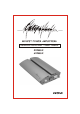
MOSFET POWER AMPLIFIERS Installation Instructions / Owner's Manual 400MSX 600MSX
INTRODUCTION Congratulations on your purchase of a California state-of-the-art power amplifier. Your selection of a California car audio product indicates a true appreciation of fine musical reproduction. Whether adding to an exi sting system or including your California amplifier in a new system, you are certain to notice immediate performance benefits. KEEP YOUR SALES RECEIPT Take this time to attach your sales receipt to the manual and put in a safe place.
SAFETY PRECAUTIONS Fuse amplifier's power wire at the battery. Be sure to fuse the power wire within 12" of the car's battery. This will protect the car's battery in case of a short circuit between the power amplifier and battery. THIS IS A MUST, the amplifier's built-in fuse will only protect the power amplifier not the car's battery! Use high grade wire connectors. To ensure maximum power transfer and secure safe connections, it is recommended to use high grade connectors where needed.
FEATURES AND BENEFITS DC Offset Protection This circuit protects the output of the amplifier against DC voltage. If for some reason DC voltage is detected at the output stage, the amplifier will shut down protecting the speakers from direct current. Short Circuit Protection The circuit protects the amplifier from damage due to a short found in the speakers or wiring. If one of the speakers or its wiring comes in contact with ground, the amplifier will shut down.
Power Fusing This protects the amplifier against short circuits and excessive current. Remote Turn-on Automatically turns amplifier on when connected to the head unit's remote output. The amplifier will turn on and off with the head unit to save current consumption. This control also operates the reset circuit for the amplifier's protection. It must be connected with the head unit in order to reset protection circuits.
MOUNTING LOCATION Before you start the installation, it will be necessary to find a mounting location for the amplifier. Find a location in which the amplifier will receive adequate ventilation in order to dissipate the heat it develops during operation. Two popular mounting locations are in the trunk or under the seat. Select the location in which you wish to mount the amplifier.
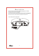
POWER CONNECTIONS Speaker Output B+ GND REM Fuse IN-LINE POWER FUSE MOUNTED WITHIN 12" FROM BATTERY RECOMMENDED RADIO'S REMOTE TURN-ON OUTPUT (NOT PROVIDED) - + CAR BATTERY +12V 94.7 IMPORTANT! Before making any connections, disconnect the car's battery until the installation is completed to avoid possible damage to the electrical system. Connect the amplifier to the car's battery.
SIGNAL CONNECTIONS Connect the output of the head unit (AM/FM cassette player, CD, or DAT) to the RCA input terminals of the amplifier. To make these connections, we recommend high quality RCA cables, which are available at your local car audio retailer. Run signal wires away from electrical wires to avoid possibility of induced noise from the car's electrical system (i.e. popping noises or engine noise).
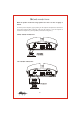
HIGH LEVEL CONNECTIONS (OPTIONAL) If a low level RCA signal source is not available, you may still wire the amplifier with high-level or speaker level outputs from your head unit. However, only speaker leads from a "floating ground" system may be used (see diagram below). Use the provided plug to make the following connections . Note: The speaker leads from a "common ground" head unit systems should not be connected to the hi-level input terminals of the following connections.
SPEAKER CONNECTIONS Make the speaker connections using speaker wire that is at least 10 gauge or heavier. As with any audio component, proper phasing of the amplifier and speakers is essential for strong bass response. When connecting, make sure that positive (+) from the amplifier is connected to the positive (+) of the speaker, and the same for negative (-).
SETTING THE CROSSOVER AND BASS BOOST Select your crossover type and frequency. The amplifier is equipped with a built-in variable low -pass crossover network allowing you to select the desired crossover point for your subwoofers. Please refer to speaker manufactures recommended crossover point. Bass Boost LP X-over 85 40 130 0 Select the crossover point for your speakers. 12 You can add up to 12dB bass boost by increasing the Bass Boost control.
TROUBLE SHOOTING THE SYSTEM We have put together this trouble-shooting guide if you experience problems after installing the amplifier. Please keep in mind that the majority of problems incurred are caused by improper installation and not the equipment itself. In addition, there are many components in the system that could cause various signal problems such as inducted electrical noise and engine noise.
SPECIFICATIONS Max Power @ 4 Ohm RMS Power @ 4 Ohm Max Power @ 2 Ohm RMS Power @ 2 Ohm THD @ RMS Power Frequency Response Signal To Noise RCA Input Sensitivity RCA Input Impedance High Level Input Impedance Load Impedance Crossover Type (12dB/Octave) Crossover Frequency (Variable) Bass Boost @ 45Hz (Variable) Damping Factor Power Terminal Size Speaker Terminal Size Fuse Value (ATC/ATO Type) Size (H x D x W) 400MSX 600MSX 1 x 400W 1 x 200W 1 x 600W 1 x 300W <0.
LIMITED WARRANTY Profile Consumer Electronics, Inc. warrants this product to be free from defects in material and workmanship for a period of One (1) Year from the date of sale to the original consumer purchaser. If this product is proven to be defective within this one year period, Profile will repair it when said product is returned, with a copy of the dated sales receipt, freight prepaid to Profile. This warranty is valid only in the United States.
WARRANTY REPAIR POLICY In the unlikely event of product failure, the following procedures should be followed 1) The unit must be under the 1-year warranty period. 2) The unit must have no physical damage. 3) A copy of the original proof of purchase must be sent with the unit. 4) Include a brief description of the problem or failure with the unit. 5) Include the return street address and daytime telephone number. 6) Allow 2~3 weeks for repair (this period includes shipping time).
By PROFILE CONSUMER ELECTRONICS, INC. 15060 SHOEMAKER AVE SANTA FE SPRINGS, CA 90670 TEL: (562)404-9393 FAX: (562)404-9433 WWW.PROFILEUSA.