MOSFET POWER AMPLIFIERS Installation Instructions / Owner's Manual CL300 CL400 CL440 CL600 CL640 CL800 CL1200 CL600M
INTRODUCTION Congratulations on your purchase of a Clarus state-of-the-art power amplifier. Your selection of a Clarus car audio product indicates a true appreciation of fine musical reproduction. Whether adding to an existing system or including your Clarus amplifier in a new system, you are certain to notice immediate performance benefits. KEEP YOUR SALES RECEIPT Take this time to attach your sales receipt to the manual and put in a safe place.
SAFETY PRECAUTIONS Fuse amplifier's power wire at the battery. Be sure to fuse the power wire within 12" of the car's battery. This will protect the car's battery in case of a short circuit between the power amplifier and battery. THIS IS A MUST, the amplifier's built-in fuse will only protect the power amplifier not the car's battery! Use high grade wire connectors.
FEATURES AND BENEFITS DC Offset Protection This circuit protects the output of the amplifier against DC voltage. If for some reason DC voltage is detected at the output stage, the amplifier will shut down protecting the speakers from direct current. Short Circuit Protection The circuit protects the amplifier from damage due to a short found in the speakers or wiring. If one of the speakers or its wiring comes in contact with ground, the amplifier will shut down.
Bass Boost For added low frequency performance the amplifiers are equipped with a variable 0~18 dB bass boost @ 45Hz. Line Out One set of full range line outputs have been provided for convenient connection to additional amplifiers in the system. Subsonic Filter (CL1200 & CL600M Only) A subsonic filter has been provided to filter out unwanted low bass frequencies below the audible range.
MOUNTING LOCATION Before you start the installation, it will be necessary to find a mounting location for the amplifier. Find a location in which the amplifier will receive adequate ventilation in order to dissipate the heat it develops during operation. Two popular mounting locations are in the trunk or under the seat. Select the location in which you wish to mount the amplifier.
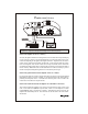
POWER CONNECTIONS RADIO'S REMOTE TURN-ON OUTPUT - + CAR BATTERY +12V 94.7 IMPORTANT! Before making any connections, disconnect the car's battery until the installation is completed to avoid possible damage to the electrical system. Connect the amplifier to the car's battery. At times, the amplifier will need to draw large levels of current that cannot be provided by any circuit in the car's fuse box.
SIGNAL CONNECTIONS Connect the RCA output of the head unit (AM/FM cassette player, CD, or DAT) to the RCA input terminals of the amplifier. To make these connections, we recommend high quality RCA cables, which are available at your local car audio retailer. Run signal wires away from electrical wires to avoid possibility of induced noise from the car's electrical system (i.e. popping noises or engine noise).
HIGH LEVEL CONNECTIONS (OPTIONAL) High Level inputs have been included to connect the amplifier to a radio without low-level outputs (i.e. factory radio). This connection will allow you to connect directly to the speaker output of the radio with out the need of an external adapter. Determine the type of radio you have and make one of the following connections. CAUTION! Before making any connections determine the type of radio to avoid possible damage to amplifier and/or radio.
9
SPEAKER CONNECTIONS Make the speaker connections using speaker wire that is at least 14 gauge or heavier. As with any audio component, proper phasing of the amplifier and speakers is essential for strong bass response. When connecting, make sure that positive (+) from the amplifier is connected to the positive (+) of the speaker, and the same for negative (-).
SPEAKER CONNECTIONS (BRIDGED) The Clarus amplifiers are capable of being bridged in a mono configuration. This feature allows you the flexibility of using the amplifier to drive a ** subwoofer or a center channel. In this configuration the amplifier sums the right and left channel to deliver one channel (mono) output. Please note: in order for the amplifier to sum right and left signal information, both right and left RCA connections must be made.
SPEAKER CONNECTIONS (TRI-MODE) The amplifier is capable of running in a Mono / Stereo mode. This feature gives the amplifier the ability to run stereo satellites (midbass & tweeter) simultaneously with a mono subwoofer. These connections are more complicated because they require the use of passive crossover networks (Not provided) to divide the frequencies to the speakers. We have included a sample diagram for 4 Ohm connections.
ADJUSTING THE X-OVER, BASS AND SUB SONIC FILTER . (Please note: If you intend to us e the amplifier in the Tri-mode configuration, it is necessary to set the crossover control to the "FULL" setting in order to receive full range output) The Clarus amplifiers are equipped with a built-in variable crossover network allowing you to select the crossover type (i.e. Low-Pass or Hi-Pass) and the desired crossover point.
TROUBLE SHOOTING THE SYSTEM We have put together this trouble-shooting guide if you experience problems after installing the amplifier. Please keep in mind that the majority of problems incurred are caused by improper installation and not the equipment itself. In addition, there are many components in the system that could cause various signal problems such as inducted electrical noise and engine noise.
SPECIFICATIONS CL300 Output Power @ 4 Ohm RMS Power @ 4 Ohm RMS Power @ 2 Ohm Bridged RMS @ 4 Ohm THD @ RMS Power Frequency Response Signal To Noise Stereo Separation RCA Input Sensitivity RCA Input Impedance High Level Input Impedance Load Impedance Stereo Load Impedance Bridged Crossover Type (12dB/Octave) Crossover Frequency (Variable) Bass Boost @ 45Hz (Variable) Damping Factor Power Terminal Size Speaker Terminal Size Fuse Value (ATC/ATO Type) Size (H x D x W) CL400 2 x 150W 2 x 75W 2 x 110W 1 x 225W
SPECIFICATIONS CL440 Output Power @ 4 Ohm RMS Power @ 4 Ohm RMS Power @ 2 Ohm Bridged RMS @ 4 Ohm THD @ RMS Power Frequency Response Signal To Noise Stereo Separation RCA Input Sensitivity RCA Input Impedance High Level Input Impedance Load Impedance Stereo Load Impedance Bridged Crossover Type (12dB/Octave) Crossover Frequency (Variable) Bass Boost @ 45Hz (Variable) Damping Factor Power Terminal Size Speaker Terminal Size Fuse Value (ATC/ATO Type) 4 x 100W 4 x 50W 4 x 75W 2 x 150W <0.
LIMITED WARRANTY Profile Consumer Electronics, Inc. warrants this product to be free from defects in material and workmanship for a period of One (1) Year from the date of sale to the original consumer purchaser. If this product is proven to be defective within this one year period, Profile will repair it when said product is returned, with a copy of the dated sales receipt, freight prepaid to Profile. This warranty is valid only in the United States.
WARRANTY REPAIR POLICY In the unlikely event of product failure, the following procedures should be followed 1) The unit must be under the 1-year warranty period. 2) The unit must have no physical damage. 3) A copy of the original proof of purchase must be sent with the unit. 4) Include a brief description of the problem or failure with the unit. 5) Include the return street address and daytime telephone number. 6) Allow 2~3 weeks for repair (this period includes shipping time).
By PROFILE CONSUMER ELECTRONICS, INC. 17625 FABRICA WAY CERRITOS, CA 90703 TEL: (714) 690-4949 FAX: (714) 690-4957 WORLD WIDE WEB: WWW.PROFILEUSA.