
Operation Manual


CONTROL BOX
9
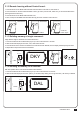
6.2 Function of the LED display
LED Display Programmable Functions LED Display Programmable Functions
5). Safety For Gate Operation
6). LED Indication
4). Gate Operation Logic
(A) In gate-opening phase: The gates stop if the transmitter/push button/key selector is activated, and close when
the transmitter/push button/key selector is reactivated.
(B) In gate-closing phase: The gates stop if the transmitter/push button/key selector is activated, and open when
the transmitter/push button/key selector is reactivated.
When the gate is opening, the LED Display
show ‘OPN’ for 2s and then change to Amp
current indication
When the gate is stopped, the LED Display show
‘STP’ until next commend has been made, after
10s no further movement, the LED turns to OFF
When the gate is closing, the LED Display show
‘CLS’ for 2s and then change to Amp current
indication
LED display shows “S01” means the panel did not
detected the M1+/M1 and M2+/M2 both been
connected before the system learning procedure,
check for 2 motors’ wire connection, for dual gate
system
The memory of the system is all deleted/cleaned
by press and hold the UP + SET+ DOWN button
together for 5s and the panel will be back to
default settings
LED display shows “S02” means the panel did not
detected the M1+/M1 but detected M2+/M2 been
connected, notice the installer to check the motor
wire connection, if this is single gate system,
motor wire should connect to M1+/M1 not on
M2+/M2
LED display show “S03” means same button on
the remote has been identified for more than 2
functions
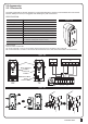
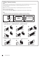
AC INPUT
1
1
23456
AC INPUT
1
1
23456
Antenna
1 2 3 4 5 6 7 8
9 10 11 12 13 14 15 16 17 18
19 20 21 22 23 24 25 26
Lit+ Lit- Lat+ Lat- M1+ M1- M2+ M2- 5V S1 S2 GND Lmt1 Lmt2 GND Lmt3 Lmt4 GND GNDPh1 Ph2PhVcc PhVccGNDDKey SKey
6.1 LED Lighting
Blue LED System Learning: Blue LED in receiver board blinks two times when learning is completed.
LED2 RF : Key selector, or the push button is activated, LED2 will be on.
LED4 Ph1 : LED4 will be on when Ph1 are triggered.
LED3 Ph2 : LED3 will be on when Ph2 are triggered.
M2-M1-
Lat-
Lit-
Lmt4Lmt3
Lmt2
Lit+ SKey
S1
M2+
M1+Lat+ Ph2Ph1 PhVcc PhVcc
S25V
DKey GND
GND
GND
GND
Lmt1
GND
LED 2 LED 4 LED 3
[LEA] means motor into the system learning
mode, do not interrupt during this procedure
[D-G] means motor completed the learning
procedure for dual gate installation
[S-G] means motor completed the learning
procedure for single gate installation
In gate-opening phase: For safety purpose, the gates stop if encountering obstacles.
In gate-closing phase: For safety purpose, the gates reverse for 2 sec if encountering obstacles.