
Operation Manual
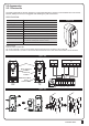


CONTROL BOX
10
7.2 Parameter
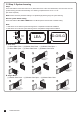
7.1 Parameter Learning
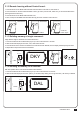
7). Parameter Modification
LED Display Definition Parameter Table Description
Motor Type
Overcurrent for Gate Opening
Overcurrent for Gate Closing
Motor Speed for Opening
Motor Speed for Closing
Deceleration Speed
Time Gap b/w Two Gates
(Opening)
F1
F2
F3
F4
F5
F6
F7
F1-1
F1-2
F1-3
F2-1
F2-2
F2-3
F2-4
F3-1
F3-2
F3-3
F3-4
F4-1
F4-2
F4-3
F4-4
F5-1
F5-2
F5-3
F5-4
F6-1
F6-2
F6-3
F6-4
F7-0
F7-1
F7-2
F7-3
F7-4
F7-5
F7-6
F7-7
F7-8
F7-9
Overcurrent
Limit Switch
Hall Sensor
2A
3A
4A
5A
2A
3A
4A
5A
40%
50%
75%
100%
40%
50%
75%
100%
40%
50%
60%
70%
0 sec
2 sec
5 sec
10 sec
15 sec
20 sec
25 sec
35 sec
45 sec
55 sec
1. The factory setting is "F1-1"
1. The factory setting is "F2-2".
1. The factory setting is "F3-2".
1. The factory setting is "F4-3".
1. The factory setting is "F5-3".
1. The factory setting is "F6-2".
1. The factory setting is "F7-1".
Press “UP+SET” for 3 seconds to get
into the program setting display from F1.
Press “UP” or “DOWN” to change
setting item from F1 to FJ .
Press “SET” button again to get into
the sub-settings
Press “UP” or “DOWN” to change
Push from F1-1 to F1-3.
Press “SET” button again to
confirm.
Push
91011121314
LED1
LED2
LED3
ON
OFF
UP
SET
DOWN
Push
AC INPUT
1234567891011121314
1
23456
LED1
LED2
LED3
ON
OFF
UP
SET
DOWN
Push
AC INPUT
1234567891011121314
1
23456
LED1
LED2
LED3
ON
OFF
UP
SET
DOWN
Push
91011121314
LED1
LED2
LED3
ON
OFF
UP
SET
DOWN
Push
AC INPUT
1234567891011121314
1
23456
LED1
LED2
LED3
ON
OFF
UP
SET
DOWN
1 2
4 5
3